
Simple Audio Clipper/Limiter
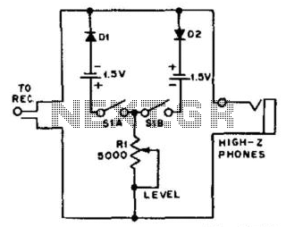
The circuit is designed to enhance audio quality by preventing distortion caused by excessive signal levels. It utilizes a 5-kOhm potentiometer to adjust the clipping threshold, allowing users to tailor the audio output according to their preferences and the characteristics of the input signal. The potentiometer functions as a variable resistor, enabling fine-tuning of the clipping level, which is crucial for protecting headphones from damage due to high audio levels.
The noise clipper operates effectively on low duty cycle pulse-type noise, which is common in various electronic environments, particularly those influenced by ignition systems in vehicles. By targeting this specific type of noise, the circuit ensures that audio clarity is maintained while unwanted spikes are mitigated.
In this configuration, the resistor Rl plays a vital role in setting the bias for the diodes used in the clipping stage. The diodes are arranged to conduct when the audio signal exceeds a certain threshold, thus limiting the output to a safe level. The value of Rl is critical, as it influences the forward voltage drop across the diodes, determining the point at which clipping occurs.
The overall design of the circuit ensures that it is compact and suitable for integration into headphone amplifiers or other audio devices, providing an effective solution for managing noise and enhancing the listening experience. Proper implementation of this circuit can significantly improve the performance of audio systems in environments with high electromagnetic interference. For use with headphones, this circuit sets the audio clipping level via a 5-KOhmhm pot. This type of noise cli pper works best for pulse-type noise of low duty cycle, such as ignition noise. Rl sets the bias on the diodes for the desired limiting level. 🔗 External reference
Related Circuits
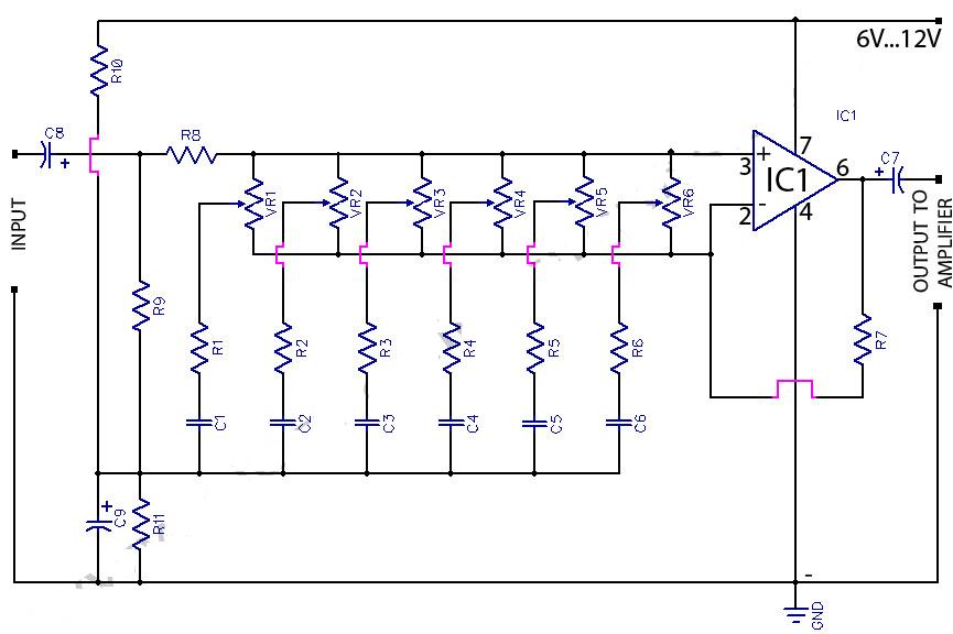
This circuit is a 6-band graphic equalizer that allows for the adjustment of low, medium, and high frequencies using the operational amplifier circuit 741. It enables control and mixing of frequencies and tones according to user preferences. The audible...
The compact, low-cost condenser microphone audio amplifier described here provides high-quality audio output of 0.5 watts at 4.5 volts. It can be utilized in intercom systems, walkie-talkies, low-power transmitters, and packet radio receivers. Transistors T1 and T2 constitute the...
The diagram illustrates a simple and efficient receiver designed for activating garage doors, starter motors, alarms, warning systems, and various other applications. The SCR utilized in this circuit features an extremely low trigger current of 30 µA, requiring only...
Can be directly connected to CD players, tuners and tape recorders. Simply add a 10K Log potentiometer (dual gang for stereo) and a switch to cope with the various sources you need. A correct grounding is very important to...
The mixer allows for the addition of multiple channels as needed. This can be accomplished by simply duplicating the input sections that are clearly indicated on the schematic. One variant of this mixer was observed to have 25 inputs. The...
The circuit biases the BC558 transistor, causing LED D1 to flash in response to signals from the remote control. The preset resistor in the circuit sets the sensitivity level. The circuit utilizes a BC558 PNP transistor, which plays a crucial...