
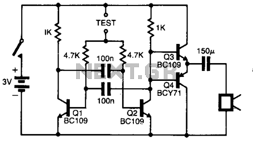
Simple Remote Control Tester

The circuit utilizes a BC558 PNP transistor, which plays a crucial role in controlling the LED's operation based on the input signals received from a remote control unit. The BC558 is biased to operate in its active region, allowing it to amplify the small signals coming from the remote control, which can be infrared or radio frequency signals depending on the design.
The LED D1 serves as an indicator, illuminating to show that a signal has been received and processed by the circuit. The flashing of the LED is directly correlated to the frequency and duration of the signals transmitted by the remote control, providing a visual cue of the communication activity.
A preset resistor is incorporated into the circuit to adjust the sensitivity of the BC558 transistor. By varying the resistance, the threshold for signal detection can be modified, allowing the circuit to be fine-tuned for optimal performance in different environments or with different remote control units. This adjustment is essential for ensuring that the circuit can effectively respond to the intended signals without being triggered by noise or interference.
Overall, this simple yet effective circuit design demonstrates the fundamental principles of transistor operation, signal amplification, and visual feedback through LED indicators, making it suitable for various applications in remote control systems.In the circuit here it simply biases the BC558 which, in turn, makes LED D1 flash in sympathy with the telegram from the remote control. The preset in the circuit determines the sensitivity. 🔗 External reference
Related Circuits
Questions frequently arise regarding the use of solar panels to power Fiber-To-The-Home (FTTH) equipment. This concept may seem unusual at first, but it is a practical solution for numerous businesses and municipalities. For instance, many municipalities have water towers,...
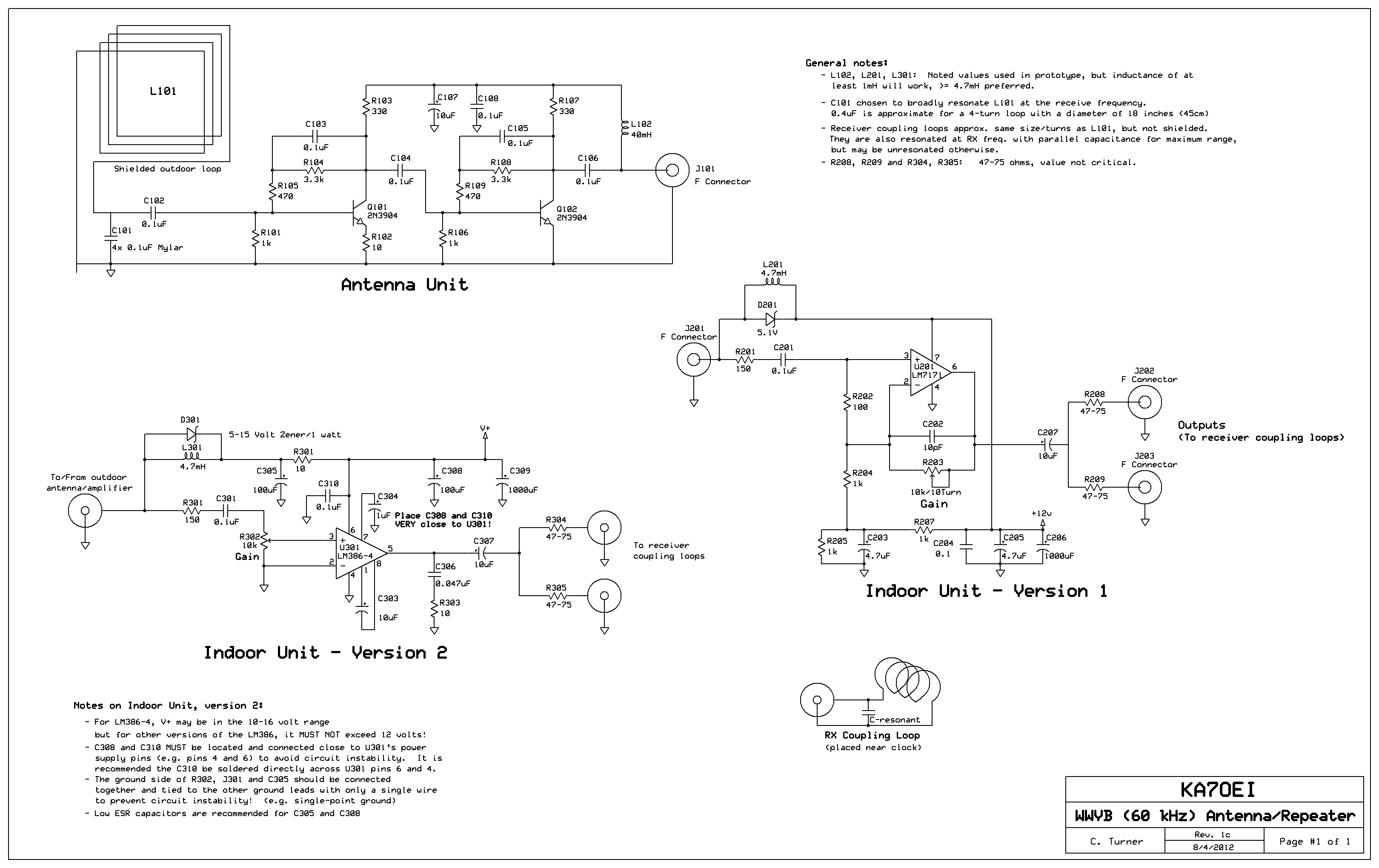
Inside the outdoor box where the loop is mounted, the amplifier circuitry is displayed. The four capacitors located at the lower-left corner of the perfboard are used to broadly resonate the receive loop. In the office building, which is...
The pitch of the tone is dependent upon the resistance under test. The tester will respond to resistance of hundreds of kilohms, yet it is possible to distinguish differences of just a few tens of ohms in low-resistance circuits....
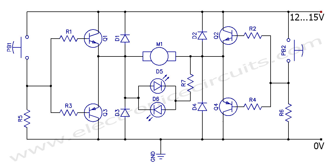
This circuit can control the direction of a DC motor, allowing it to operate in both clockwise and counterclockwise directions (forward and backward). The described circuit employs an H-bridge configuration, which is essential for reversing the polarity of the voltage...
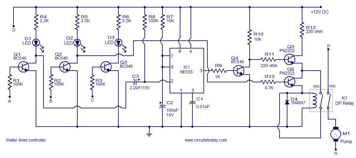
A simple water level controller circuit utilizing a 555 integrated circuit (IC) and six transistors. A relay is employed for controlling the pump motor. This water level controller circuit is designed to monitor and manage the water level in a...
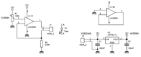
This led tester uses a power switched op-amp. The control range is about 0-30mA. Thus, all test and standard LEDs, the voltage across the LED to read. The power supply is an example lab power supply at least 15V,...