
Simple Audio Peak Detector
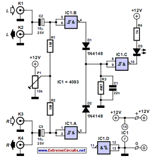
The audio peak detector circuit is designed to provide a visual indication of the peak levels in audio signals, making it particularly useful in audio processing and mixing applications. The circuit typically consists of two main sections: the signal input stage and the peak detection stage.
In the signal input stage, the audio signals from the left and right channels are fed into the circuit. Each channel's signal is first buffered and then processed to ensure that it is at the appropriate level for detection. This may involve the use of operational amplifiers configured as voltage followers or gain stages to maintain signal integrity.
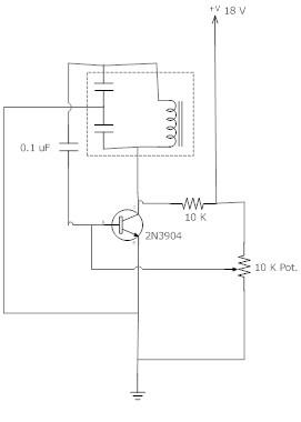
The peak detection stage employs a diode and capacitor arrangement to capture the peak voltage of the incoming audio signal. The diode allows current to flow only in one direction, charging the capacitor to the peak voltage level. A resistor may be placed in parallel with the capacitor to provide a discharge path, allowing the capacitor to reset after the peak has been indicated.
To combine the output of both channels for monitoring with a single LED, the circuit may utilize a summing amplifier or a simple resistor network. This ensures that the highest peak from either channel is represented by the LED. The LED will illuminate when the voltage across it exceeds a certain threshold, indicating that a peak has been detected.
The design can be further enhanced by incorporating additional features such as adjustable sensitivity, which can be achieved through variable resistors in the circuit, or by adding a filter to limit the response to specific frequency ranges. This flexibility allows the audio peak detector to adapt to various audio environments and requirements.
Overall, the audio peak detector circuit is a valuable tool for audio engineers and musicians, providing essential feedback on audio levels and ensuring optimal performance during mixing and live sound applications.This audio peak detector allows a pair of stereo channels to be monitored on a single LED. Identical circuitry is used in the left and right channels. Use.. 🔗 External reference
Related Circuits
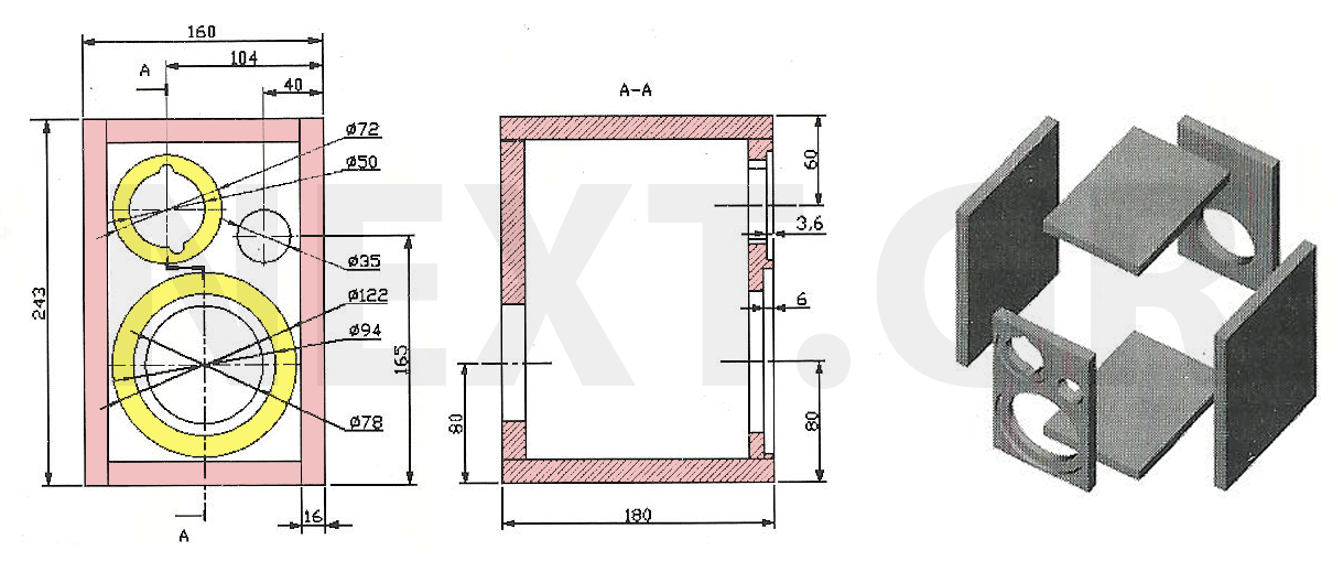
The speakers presented are notable for their compact size and exceptional sound quality. Often, home spaces are limited, making large speakers impractical. However, this does not imply a compromise on sound quality. The design is straightforward, cost-effective, and easy...
The TDA 2030 audio amplifier is capable of delivering 20 W of output power; however, in this schematic, the output power has been reduced to 8 W, and 10 W speakers are utilized. The input sensitivity is approximately 200...
When the phototransistor is illuminated by infrared (IR) light, it begins to conduct, causing the voltage between a 1 MΩ resistor (chosen arbitrarily) and the phototransistor to decrease from VCC to lower values. When this voltage falls below VCC/3,...
The frequency remains stable as the voltage decreases. It is referred to as the "backwards JT" because it operates optimally with a bifilar coil and a single transistor. With a modification to the circuit, it is possible to deplete...
Is there a way to automatically turn on an LED when it gets dark? A version was created using a relay and photoresistor that functioned properly, but concerns arose regarding potential battery drain. The project aims to integrate with...
Simple circuitry suitable for moving-magnet cartridges. Passive high-frequency equalization. This simple but efficient circuit devised for cheap moving-magnet cartridges can be used in connection with the audio power amplifiers shown in these webpages, featuring low noise, good RIAA frequency...