
LED Battery Checkers
When voltage drops below the preset threshold, the voltage on the wiper of R2 drops below 2.5 volts, and the TL431 conducts less current, only up to about 1 milliamp, and the anode voltage rises until the LED conducts.
I tested this with a 6 volt threshold rather than a 5.4 volt threshold. When adjusted for a 6 volt threshold, the LED turns on at 6.0 volts and then slowly fades out as the battery voltage decreases, until it reaches about 2.5 volts, when the LED is too dim to see. The LED is off above 6.0 volts, but (for reasons I have not investigated) the LED comes back on at voltages above 8.35 volts. The come back on voltage is proportional to the threshold setting, thus, if the circuit were adjusted to turn on the LED when the voltage dropped below 12 volts, the LED would also come on at voltages above (8.35/6) x 12 = 16.7 volts.
The minimum voltage across the TL431 is 2.5 volts, which would still leave enough to illuminate D2 (which requires about 1.8 volts), so D1 was added to provide an additional 0.7 volt drop in series with D2 so that D2 will not illuminate when the TL431 is sinking the maximum current.
These circuits can also be adjusted for other battery voltages and other types of battery. This circuit should work well with Nickel Cadmium (ni-cd or nicad), Nickel Metal Hydride (NIMH) or other rechargeable as well as primary cells types such as Carbon-Zinc and Alkaline. Just make sure that you don't exceed the ratings of the parts for your particular application.
The practical minimum threshold voltage for the Battery Low circuit is about 3.5 volts while the practical minimum voltage for the Battery Good circuit is about 4.5 volts.
The Battery Good checker circuit employs a TL431 voltage reference as the core component for monitoring battery voltage levels. The circuit is designed to activate a green LED indicator when the voltage exceeds a specified threshold, which can be adjusted according to the battery type and application. The operational principle is based on the voltage divider formed by a potentiometer (R2) and the battery voltage, allowing for precise setting of the threshold.
When the button is pressed, the circuit checks the voltage across the battery. If the voltage is above the set threshold, the wiper of R2 will output a voltage greater than 2.5 volts, causing the TL431 to conduct and effectively shunt current away from the LED, keeping it off. Conversely, if the battery voltage falls below the threshold, the output from R2 drops below 2.5 volts, reducing the current through the TL431. This allows the anode voltage to rise, eventually enabling the LED to illuminate.
The circuit is capable of handling various battery chemistries, including lead-acid, Nickel Cadmium, Nickel Metal Hydride, and Alkaline batteries. It is essential to ensure that the components used are rated for the specific application to prevent damage or failure. The inclusion of a series diode (D1) helps to ensure that the LED (D2) does not illuminate under high current conditions, providing a safeguard for the circuit's operation.
The design allows for a minimum threshold voltage of approximately 4.5 volts for the Battery Good circuit, which can be tailored to suit the requirements of different battery types or applications. This flexibility makes the circuit a versatile solution for battery monitoring in various electronic devices.The "Battery Good" checker. When the button is pressed, the green LED will glow if the battery voltage is above the preset threshold. This version has a higher parts count than the "Battery Low" version, but a bonus is that it can drive an LED to be very bright, and the luminance is independent of the battery voltage.
The simple expedient of a jumper wire on the back of the board made it unnecessary to hold the button down for this photograph. Besides, my finger is not very photogenic. According to Mr. Lung, the lowest safe voltage across a lead acid battery while in long term storage is 2.0 volts per cell, or 6.0 volts for a 6 volt battery. Gates Energy Products, the load must be disconnected from a lead acid cell when the voltage reads 1.8 volts or less, in order to avoid damage.
For a 6 volt battery with three cells, this critical voltage is 3 x 1.8 volts = 5.4 volts. Choose your threshold depending upon your application. If there is a good chance that the battery will not be recharged soon after running down, be safe and go with the 2.0 volt per cell threshold. The TL431 has an internal threshold of 2.5 volts. Pot R2 is adjusted so that when the battery voltage equals the desired threshold, the wiper of R2 will be 1.25 volts.
When the voltage across the battery is above the preset threshold, the voltage at the wiper of R2 is above 2.5 volts, the TL431 conducts, shunting current away from the LED, keeping the LED off. When voltage drops below the preset threshold, the voltage on the wiper of R2 drops below 2.5 volts, and the TL431 conducts less current, only up to about 1 milliamp, and the anode voltage rises until the LED conducts.
I tested this with a 6 volt threshold rather than a 5.4 volt threshold. When adjusted for a 6 volt threshold, the LED turns on at 6.0 volts and then slowly fades out as the battery voltage decreases, until it reaches about 2.5 volts, when the LED is too dim to see. The LED is off above 6.0 volts, but (for reasons I have not investigated) the LED comes back on at voltages above 8.35 volts.
The "come back on voltage" is proportional to the threshold setting, thus, if the circuit were adjusted to turn on the LED when the voltage dropped below 12 volts, the LED would also come on at voltages above (8.35/6) x 12 = 16.7 volts. The minimum voltage across the TL431 is 2.5 volts, which would still leave enough to illuminate D2 (which requires about 1.8 volts), so D1 was added to provide an additional 0.7 volt drop in series with D2 so that D2 will not illuminate when the TL431 is sinking the maximum current.
These circuits can also be adjusted for other battery voltages and other types of battery. This circuit should work well with Nickel Cadmium (ni-cd or nicad), Nickel Metal Hydride (NIMH) or other rechargeable as well as primary cells types such as Carbon-Zinc and Alkaline. Just make sure that you don't exceed the ratings of the parts for your particular application. The practical minimum threshold voltage for the Battery Low circuit is about 3.5 volts while the practical minimum voltage for the Battery Good circuit is about 4.5 volts.
🔗 External reference
Related Circuits
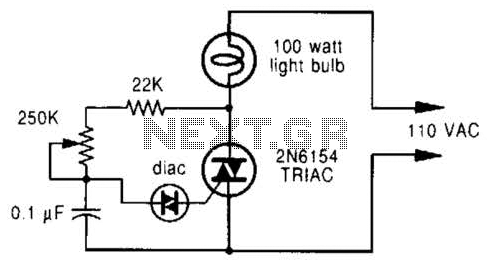
A phase-controlled dimmer delays the triac turn-on to a selected point in each successive AC half cycle. This circuit is suitable only for incandescent lamps, heaters, soldering irons, or universal motors that have brushes. A phase-controlled dimmer is an electronic...
This project flashes eight LEDs in an apparently random manner. It uses a 4060 combined counter and display driver IC which is designed for driving 7-segment LED displays. The sequence is not really random because seven of the LEDs...

A simple linear voltage-controlled amplifier can be constructed with one operational amplifier (op amp) and two junction field-effect transistors (JFETs). This amplifier can achieve an 80-dB dynamic control range with less than ±0.2% linearity error for 0 V. The described...
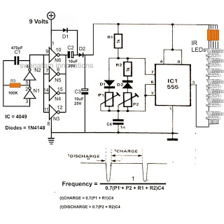
The 4049 section serves as a fundamental voltage doubler circuit, enhancing a 9 V supply to approximately 15 V. This elevated voltage subsequently acts as the supply voltage for the following 555 pulse modulator section. A key characteristic of...
This document outlines a battery monitoring circuit designed to measure the voltage of 12V lead-acid batteries, such as those used in automobiles. The circuit utilizes the LM3914 integrated circuit (IC) along with several external components, including a series of...
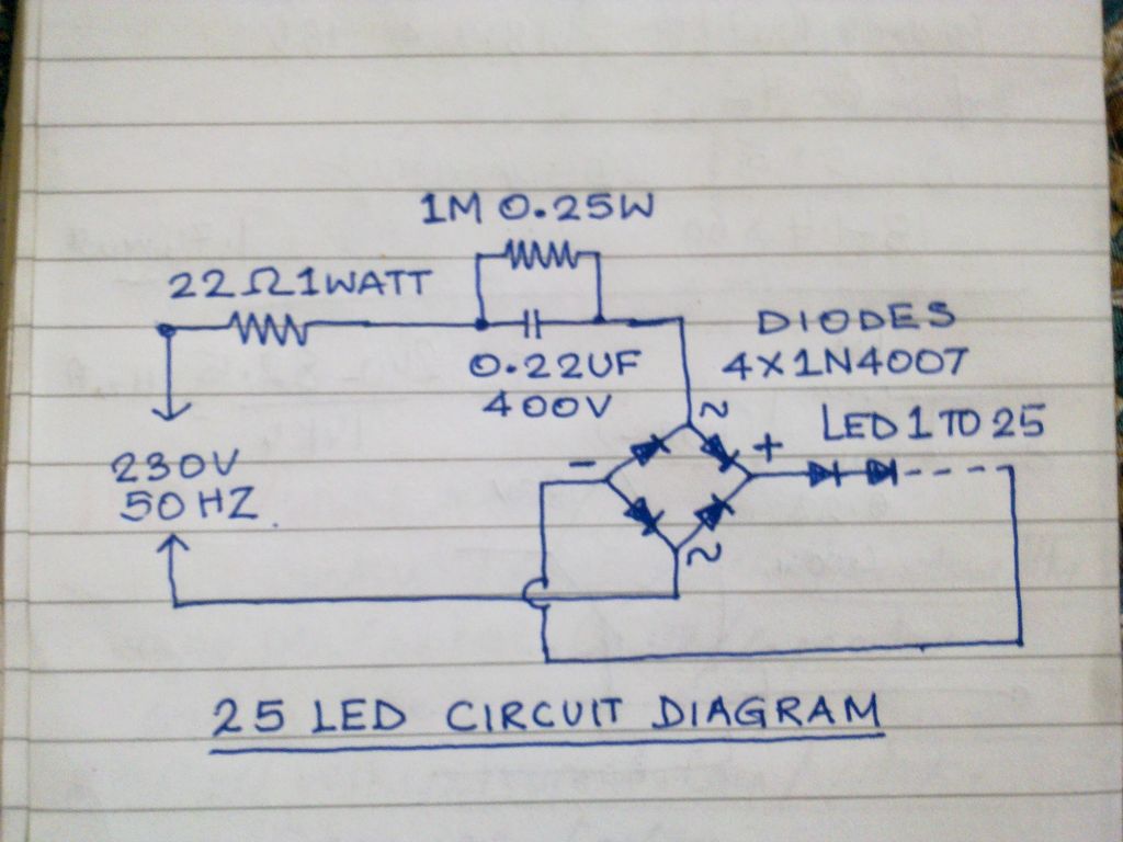
This circuit operates 25 LEDs powered by a mains supply of 230V. A fluorescent lamp adapter was acquired from a scrap dealer for ease of disassembly. The circuit consists of a series of 25 light-emitting diodes (LEDs) arranged to operate...