Simple Infrared Control Extender
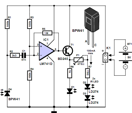
In certain situations, it is beneficial to enhance the range of available control, and this circuit serves that purpose by receiving the infrared (IR) signal from a remote control and re-transmitting it, potentially around corners or into other rooms. Photodiode D4 is connected to the inverting input of a 741 operational amplifier (opamp) through resistor R2 and capacitor C1. The BPW41 photodiode (from Vishay/Telefunken) requires reverse biasing to convert light energy into a corresponding voltage; therefore, it is also connected to the positive supply rail via resistor R1. The non-inverting input of the 741 opamp is maintained at half the supply voltage using equal resistors R3 and R4. Following the opamp, a BD240 transistor is employed as an after-burner, capable of delivering high current pulses through infrared LEDs D2 and D3. However, the pulsed current through the LD274s should not exceed approximately 100 mA; thus, a fixed resistor is utilized in series with adjustable preset P1. LED D1, a standard visible-light LED, illuminates when an IR signal is detected from the remote control. It is important to adjust P1 carefully to avoid exceeding the necessary current for the infrared emitter to effectively reach the intended destination. The mentioned currents represent peak levels due to the low duty cycle of the IR pulses, and the average current drawn from the battery will be significantly lower. The directivity of the IR LEDs, and consequently the range of the control extender, may be improved by equipping the devices with reflective caps.
This circuit operates as an infrared signal extender, primarily used to amplify and retransmit control signals from a remote device. The core component, the BPW41 photodiode, functions as a light sensor, converting incoming infrared light into an electrical signal. The operational amplifier (741) processes this signal, amplifying it to a level suitable for further transmission. The configuration of the resistors R3 and R4 ensures that the opamp operates effectively at half the supply voltage, providing a stable reference for signal amplification.
The BD240 transistor acts as a current amplifier, enabling the circuit to drive multiple infrared LEDs (D2 and D3) with sufficient current to ensure that the emitted IR signal can travel the desired distance. The inclusion of a fixed resistor in series with the adjustable preset P1 allows for fine-tuning of the current delivered to the LEDs, preventing excessive current that could damage the components while ensuring reliable operation.
LED D1 serves as a visual indicator, confirming the reception of an IR signal. This feedback is useful for users to understand when the system is active. The design takes into account the pulsed nature of the IR signals, where the average current consumption is minimized despite the peak currents being relatively high. To further enhance the performance of the IR LEDs, reflective caps may be added, which focus the emitted light and increase the effective range of the control extender, allowing for greater flexibility in remote control applications. Overall, this circuit is an effective solution for extending the operational range of infrared remote controls in various environments.In some cases, it is desirable to extend the range of the available control and this circuit fits the bill, receiving the IR signal from your remote control and re-transmitting it, for example, around a corner into another room. Photodiode D4 is connected to the inverting input of a 741 opamp through resistor R2 and capacitor C1.
Since the BPW41 photodiode (from Vishay/Telefunken) needs to be reverse-biased to turn light energy into a corresponding voltage, it is also connected to the positive supply rail via R1. The non-inverting input of the 741 is held at half the supply voltage by means of equal resistors R3 and R4.
The opamp is followed by a BD240 after-burner transistor capable of supplying quite high current pulses through IR LEDs D2 and D3. However, the pulsed current through the LD274s should not exceed 100 mA or so, hence a fixed resistor is used in series with preset P1.
D1 is an ordinary visible-light LED that flashes when an IR signal is received from the remote. With regard to the setting of P1, do not make the IRED current higher than necessary to reliably reach the final destination of the IR signal. Also, the currents mentioned above are peak levels due to the small duty factor of the IR pulses, the average current drawn from the battery will be much smaller.
The directivity of the IR LEDs and consequently the range of the control extender may be increased by fitting the devices with reflective caps. 🔗 External reference
Warning: include(partials/cookie-banner.php): Failed to open stream: Permission denied in /var/www/html/nextgr/view-circuit.php on line 713
Warning: include(): Failed opening 'partials/cookie-banner.php' for inclusion (include_path='.:/usr/share/php') in /var/www/html/nextgr/view-circuit.php on line 713
