
Simple Battery Charger Circuit Charges Upto 12 NiCD Cells

The circuit operates by utilizing a car battery as the power source, providing the necessary voltage and current for charging NiCd cells. The configuration allows for a flexible number of cells to be charged, accommodating varying requirements from one to twelve cells. The inclusion of switch S1 enables the user to select the appropriate charging mode, optimizing the charging process based on the number of cells in use.
Typically, the circuit includes a charging regulator to ensure that the cells are charged safely and efficiently. This regulator monitors the voltage and current delivered to the cells, preventing overcharging, which can lead to cell damage or reduced lifespan. Additionally, diodes may be implemented to prevent reverse current flow, protecting the circuit components and the battery.
For charging one to six cells, the circuit may employ a simple series connection, while for charging more cells, a parallel configuration can be utilized. This flexibility is crucial for applications requiring different capacities and charging times.
The overall design should also consider thermal management, as charging can generate heat. Adequate heat dissipation mechanisms, such as heat sinks or ventilation, should be included to maintain optimal operating conditions.
In conclusion, this charging circuit provides a versatile solution for charging NiCd cells from a car battery, accommodating various configurations and ensuring safe operation through integrated protection mechanisms.This handy circuit can be used to charge from one to 12 NiCd cells from a car battery. Up to six cells can be charged with switch S1 in the normal posit.. 🔗 External reference
Related Circuits
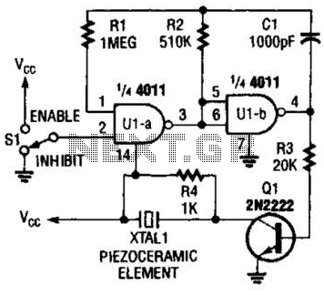
A CMOS gate and transistor buffer can be used as an effective driver for a piezoelectric transducer. The use of a CMOS gate combined with a transistor buffer offers a robust solution for driving piezoelectric transducers. CMOS technology, known for...
Oscillation is expected at the resonant frequency where the positive feedback is in phase with the input, specifically at 0 degrees. For oscillation to take place, the gain must be equal to or greater than 1 at that frequency....
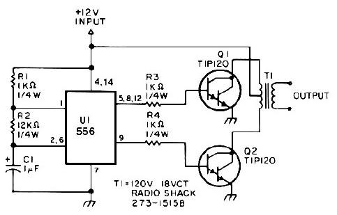
This low-power 25-watt power inverter circuit utilizes only nine electronic components. The inverter converts a DC input voltage ranging from 10V to 16V into a 60Hz, 115V square-wave power output, capable of powering AC electronic devices up to approximately...
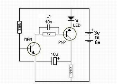
This is a simple 1.5V powered LED flasher circuit diagram. This circuit can flash 1.7V or 2.3V LEDs (depending on the color) using a 1.5V DC input. The LED will turn on when the 100µF capacitor is charged by...

A flip-flop, functioning as an astable multivibrator, can be utilized to generate timing signals in music applications such as a metronome. This can be achieved by adjusting the transistor bias resistor with a value of 100k. The astable multivibrator configuration...
Normally, an analog-to-digital converter (ADC) requires interfacing with a microprocessor to convert analog data into digital format. This involves additional hardware and software, leading to increased complexity and overall cost. The circuit of the A-to-D converter presented here is...