
Simple charge circuit porcelain
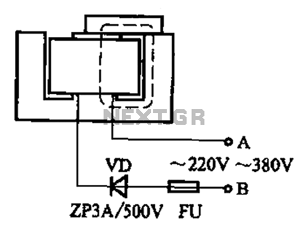
The described process involves re-magnetizing field magnets by utilizing a homemade setup that incorporates scrap components such as exchanges and contacts. The reference to models like CJ10-60 ~ 15 indicates the versatility of the components used, suggesting that various configurations can be adapted for this application. The operation at 0A implies a low-power design, which is crucial for safety and efficiency, particularly when working with high voltages such as 220V or 380V.
The omission of the term "armature" emphasizes the focus on the Yamagata core, which is likely a specific type of magnetic core material known for its magnetic properties. In the coil circuit, the inclusion of a fuse is essential for protecting the circuit from overcurrent conditions, while the diode string serves to rectify the AC voltage, allowing for controlled charging of the porcelain material used in the magnetization process.
During the magnetization phase, connecting terminals A and B to the AC power supply should be done cautiously, ensuring that safety protocols are strictly followed to prevent electrical hazards. The mention of sparks indicates the presence of high voltage, which necessitates the use of insulated tools and protective gear. The procedure specifies that the connection should only be made a limited number of times (1 or 2), which may relate to the charging cycle of the porcelain material.
Once the system shows a red indication after ten seconds, this likely signifies that the magnetization process is underway. The subsequent touches are part of the procedure to finalize the magnetization effect. Allowing the setup to remain undisturbed for several hours post-magnetization is crucial for the stability and retention of the magnetic properties achieved during the process.
Overall, this method provides a practical approach to re-magnetizing field magnets, leveraging accessible materials and components while highlighting the importance of safety and proper handling of electrical equipment.After some small loss of field magnets can be re-magnetized porcelain filled with homemade simple. Find a scrap of exchanges and contacts, and other models such as CJ10-60 ~ 15 0A (220V or 380V can), remove the word armature, only Yamagata core. In the coil circuit fuse and a diode string, they formed a charge porcelain. When magnetizing, with A, B both ends to touch 220V (nominal coil voltage of 220V) or 380V (rated coil voltage of 180V at) AC power supply (pay attention to safety), there are sparks when touched, just touch 1, 2 times. After ten seconds the red, and then touch 1,2 times, magnetization ends. Then allowed to stand for several hours and then remove (this effect).
Related Circuits
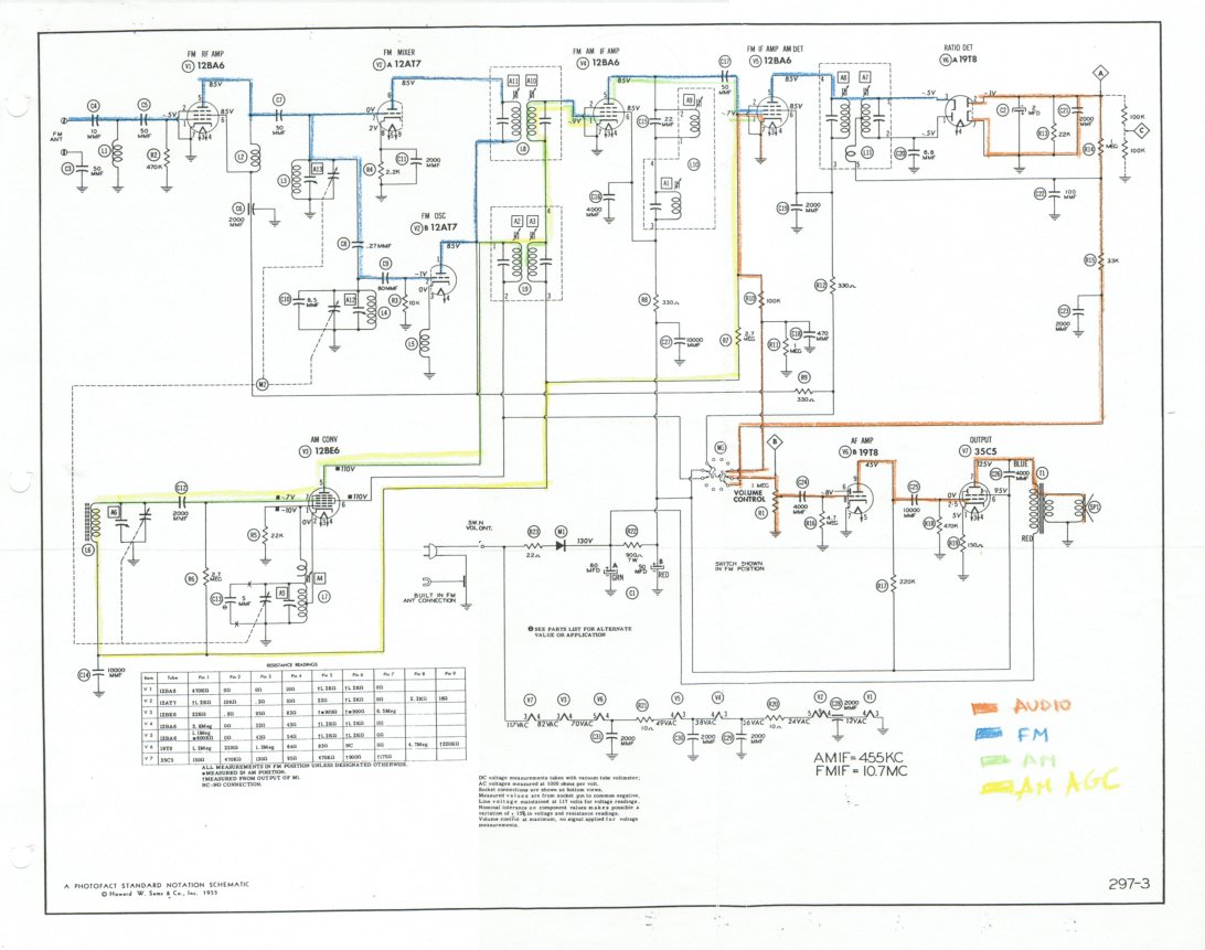
This document outlines the restoration of an antique AM/FM Granco 720 radio. It explores the design of the AM and FM receivers, detailing the alignment of these receivers, discussing repairs, and evaluating the radio's performance. The restoration of antique...

A flip-flop, functioning as an astable multivibrator, can be utilized to generate timing signals in music applications such as a metronome. This can be achieved by adjusting the transistor bias resistor with a value of 100k. The astable multivibrator configuration...
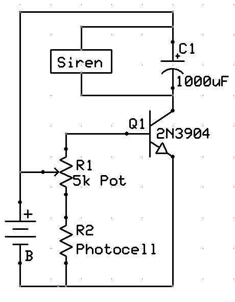
A new user has recently discovered a Laser Alarm System and has decided to explore this project. The Laser Alarm System is a security device that utilizes laser beams to detect unauthorized entry or movement within a designated area. The...
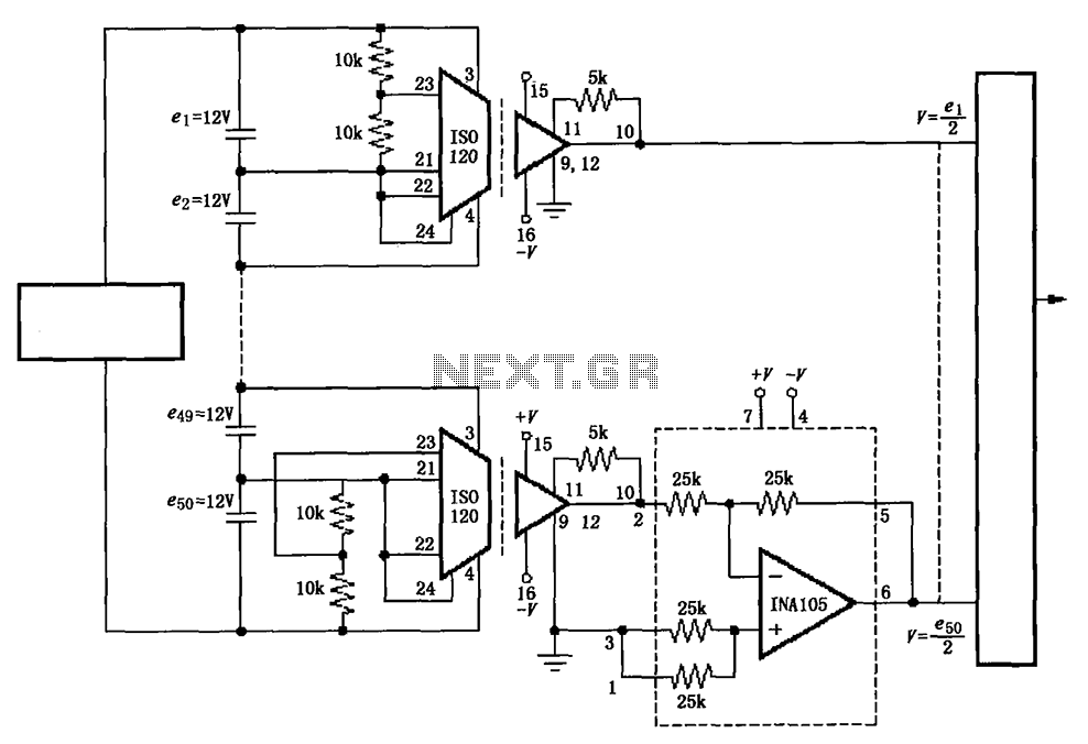
The circuit utilizes the ISO120 and INA105 instrumentation amplifiers to create a battery monitoring system for a 600V battery setup composed of 50 series-connected 12V batteries. This circuit is designed to detect charging and discharging conditions to prevent overcharging...
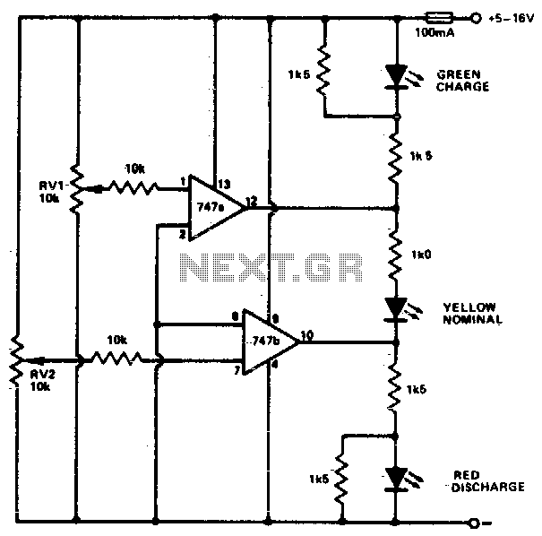
This circuit monitors car battery voltage and indicates nominal supply voltage, as well as low or high voltage conditions. RV1 and RV2 are used to adjust the thresholds at which the red/yellow and yellow/green LEDs activate or deactivate. For...
Connect a 12-volt, 20-watt lamp and a 12-volt battery to the circuit, ensuring correct battery polarity. Momentarily pressing and releasing the button will turn the lamp on. Repeatedly pressing the button will cycle through different power levels. Pressing and...