
dimmer Controller circuit
The circuit operates on a 12-volt power supply, which is connected to a lamp rated at 20 watts. This setup requires careful attention to battery polarity to ensure proper operation. The control mechanism is facilitated by a momentary push-button switch, which serves multiple functions based on the duration of the press. A brief press activates the lamp, while repeated presses enable cycling through various brightness levels, allowing users to adjust the intensity according to their preference. The functionality is further enhanced by a long press, which turns off the lamp entirely.
The design includes a microcontroller programmed with assembly code, which governs the logic for the button interactions and manages the lamp's power levels. The provided assembly code is commented for clarity, enabling users to understand and modify it as necessary. The hex code allows for easy uploading to the microcontroller, facilitating quick updates to the firmware.
Additionally, the circuit is designed with expandability in mind. It includes 11 available I/O lines, permitting the integration of more components such as additional HEXFETs for controlling multiple lamps or other devices, as well as extra buttons for more complex user interfaces. The EEPROM memory feature is particularly useful, as it can store user preferences or last-used settings, ensuring that the lamp resumes its previous state after a power interruption.
In summary, this circuit design offers a versatile and user-friendly approach to controlling a 12-volt lamp with the potential for further enhancements and customizations, making it suitable for various applications.Connect a 12 volt 20 watt lamp and 12 volt battery to the circuit (observe battery polarity). Momentarily press and release the button to turn the lamp on. Repeatedly press the button to cycle through the power levels. Pressing and holding the button will turn the lamp off. I have provided commented assembly code as well as the hex code for progra mming. Feel free to modify or add to the code as you wish. The basic circuit can easily be expanded to control additional HEXFETs, additional buttons, etc. There are 11 more I/O lines open for use. Also, the EEPROM memory could be used to "remember" settings when power is turned off. 🔗 External reference
Related Circuits
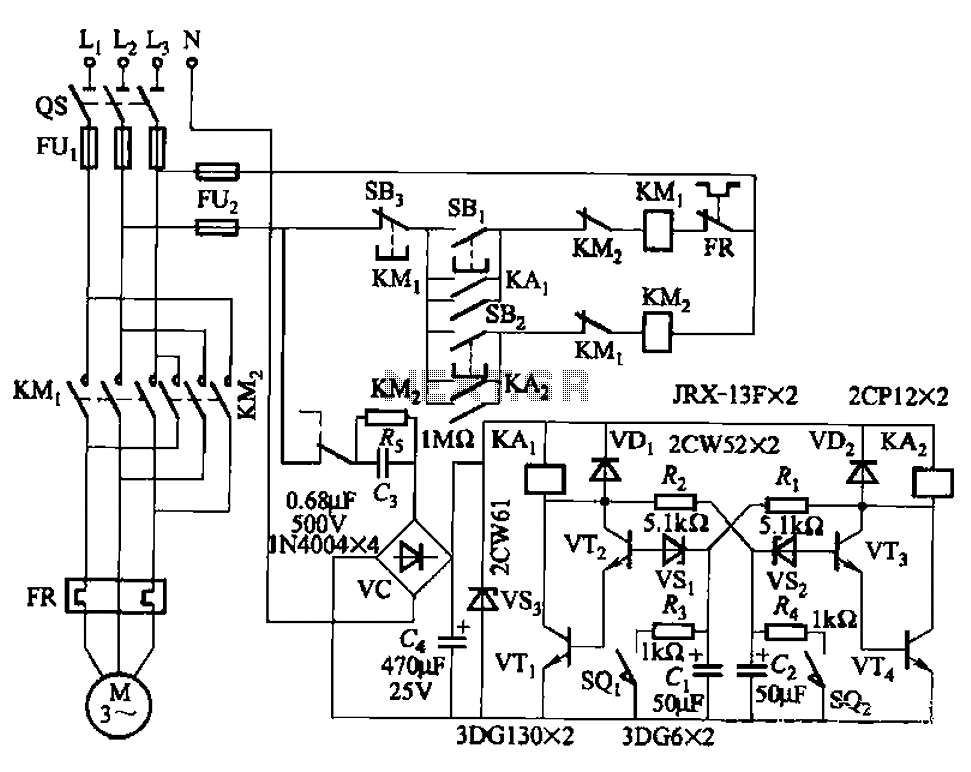
The circuit illustrated in Figure 3-72 employs a deformable bistable reversing motor control mechanism that automatically initiates and halts operation during a user-defined time delay. This feature is designed to safeguard the motor from potential impacts during the reversing...
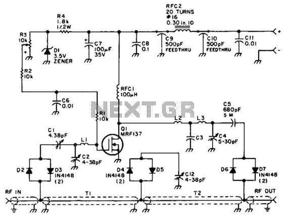
Using a power MOSFET, this amplifier can achieve a 2-W handheld radio power level, increasing it to approximately 10 W on the 2-meter band. A transmission-line RF switch is employed for transmit/receive (T/R) switching. The described amplifier utilizes a power...
Chevy S-10 Blazer Ignition Control (IC) Circuit Wiring Diagram. The Chevy S-10 Blazer ignition control circuit is a critical component in the vehicle's ignition system, responsible for managing the timing and operation of the engine's spark plugs. The circuit typically...
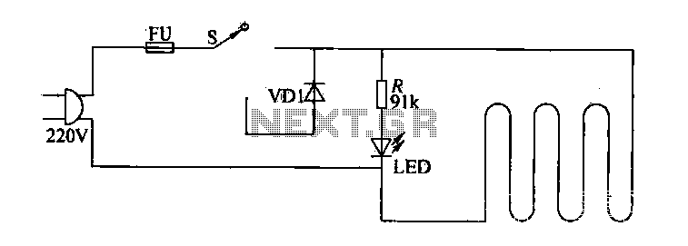
The circuit of electric blankets is controlled by switch S. When switch S is fully engaged, the entire supply voltage of 220V is applied to the heating wire, resulting in a high-temperature state. When a lower temperature is desired,...
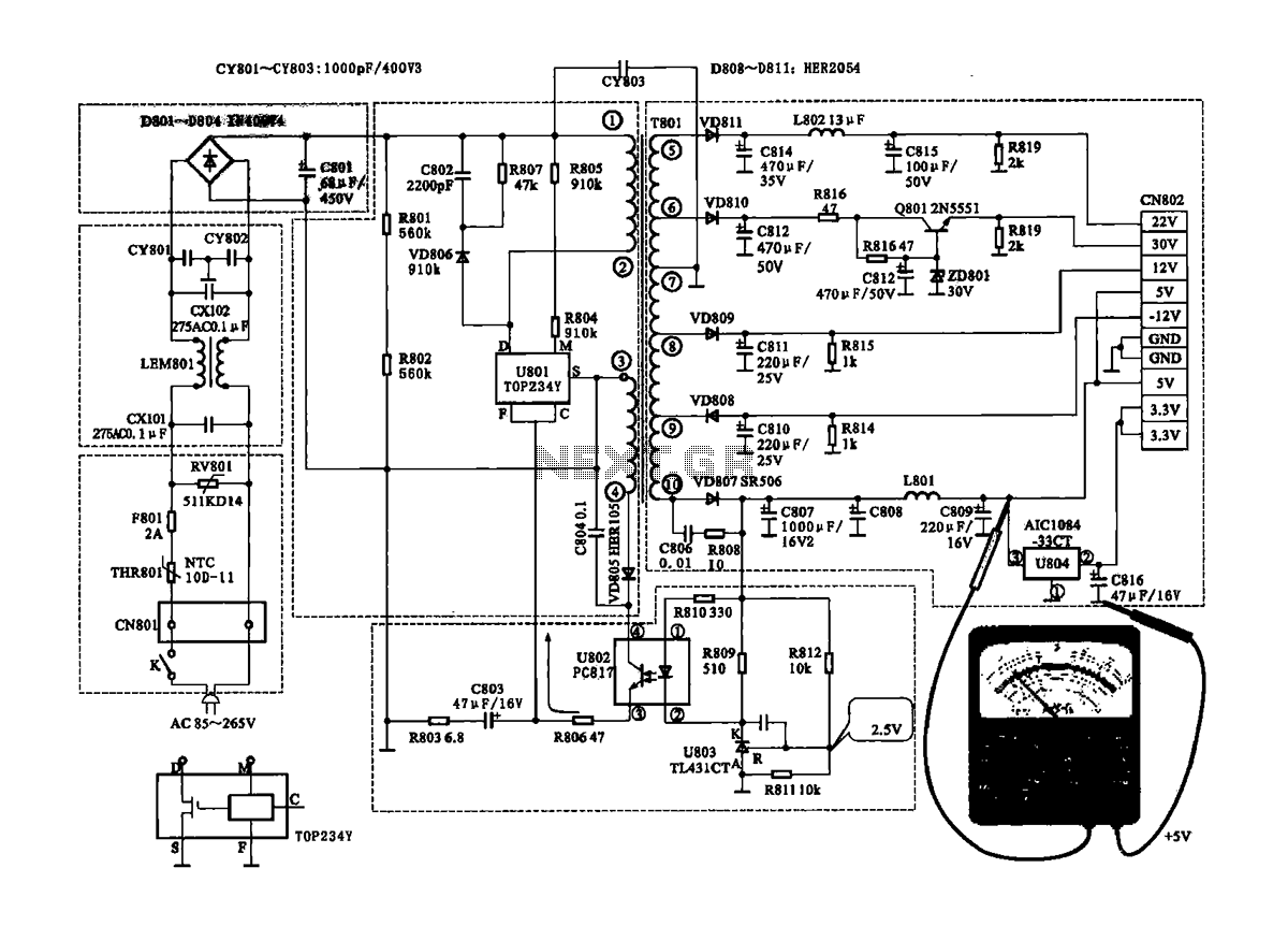
The Coship CDVB3188V receiver features a switching power supply circuit similar to the CDVB3188C model. The circuit includes several key components: an AC input circuit, an anti-jamming filter circuit, a complete flow filter circuit, and a switching oscillation circuit....
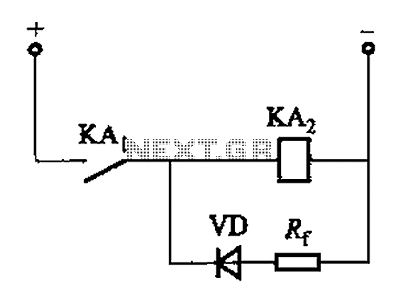
The circuit depicted in Figure 6-24 includes a relay coil with both ends connected in parallel to a resistor (Rf) or an auxiliary diode (VD). This configuration is intended to enhance power after a short circuit occurs in the...
Warning: include(partials/cookie-banner.php): Failed to open stream: Permission denied in /var/www/html/nextgr/view-circuit.php on line 713
Warning: include(): Failed opening 'partials/cookie-banner.php' for inclusion (include_path='.:/usr/share/php') in /var/www/html/nextgr/view-circuit.php on line 713