
Simple DC Charging Circuit
This circuit design primarily focuses on charging lead-acid batteries using a C-60 charge controller, which is adept at handling various power sources. The controller features intelligent functionality, allowing it to adjust the charging current based on the battery's state. During the bulk charging phase, it can deliver up to 60A, but the actual current may be limited based on the battery's capacity, typically not exceeding 20A for batteries under 100Ah to avoid voltage spikes.
The integration of a transformer is critical; two options are available with outputs of 16.4VAC and 24VAC. The selection of the transformer will influence the charging characteristics and must be compatible with the charge controller's PWM operation. It is essential to manage the inductive kick that may occur when the controller switches states, as excessive voltage could damage the components.
The capacitor plays a vital role in smoothing the output voltage and providing a buffer for current during charging. A minimum capacitance of 10,000µF is recommended to ensure stable operation, particularly under high current loads. Additionally, the circuit should incorporate protective measures, such as fuses or circuit breakers, to safeguard against overload conditions.
Proper thermal management is crucial; therefore, the chassis housing the transformer, diode, and capacitor must be adequately ventilated to prevent overheating. Heat can significantly reduce the lifespan of capacitors, making it imperative to maintain optimal operating temperatures.
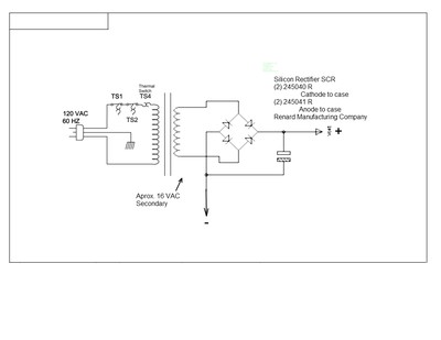
In summary, this circuit design offers a practical solution for charging lead-acid batteries, emphasizing the careful selection of components and the need for protective measures to ensure reliability and longevity in operation.Here is a simple circuit diagram I think will work for the charger. I already have the transformer, two SCRs, maybe the capacitor, heat sink, and a case to mount it all in. If you go for lead- acid batteries and forget the SCR`s, or put them in a circuits that works, you will charge your battery, even without the capacitor.
There is not a lot of u se for it. I think you are wrong on a couple of counts here. First the C-60 charge controller is intended for use with a wide variety of rather unsteady sources, no way do you need 100, 000uF, (that`s a great number for a 50A linear supply intended to supply relatively sensitive circuits) I think he could easily get a way with only 10, 000uF. Secondly the C-60 charge controller is relatively intelligent, and will ramp the current up during the bulk charge portion and one can adjust the maximum allowable charge current to a level that the 50A transformer can deliver.
Just how much the controller will deliver will also depend on the size of the battery being charged, if it`s less than 100 amp hrs I very much doubt the controller would allow more than about 20A, due to excessive voltage at the battery. The C60 wakes up in the morning as the sun rises and when the solar array has enough power available the C60 connects it to the battery.
As the battery voltage rises it will begin to regulate first giving a higher voltage for the absorption portion then dropping down to a lower voltage in the float portion and finally at night it will disconnect the solar panels to avoid reverse discharge. I think you would be better off just buying a charger. IOTA makes great chargers which are all solid state and transformerless so they are small and light yet very powerful.
I use an IOTA DLS12-75 charger for my battery bank which is charged by solar panels in the day and at night my charge controller connects the IOTA via a relay to keep the batteries full if they discharge too deeply. SimpleMind made some reference to another thread. It`s true I currently have two threads active. One trying to understand a transformer I have, supposedly out of a UPS and the other is this one. Trying to find what I had hoped would be a simple solution to a problem I have, which is living off a generator without a way to keep the batteries charged.
Oh! And the other not so small issue is I haven`t a lot of $$$ to throw at it. SimpleMind thank you for pointing out that power supply circuit as proposed would have gone up in smoke! I have done some more research and here is what I found. The controller when bulk charging is wide open to sending all of the current available up to the limit of the controller, in this case, 60amps.
The power supply will essentially see no controller while bulk charging. Herein lies the problem, most power supplies when connected to a battery will want to send a near infinite amount of current as the low internal resistance of a discharged battery will seem like a dead short to the power supply. I don`t understand though what keeps any battery charger`s transformer from doing the same. I have peeked inside a number of battery chargers, in fact I have one here and it`s certainly not any sophisticated piece of electronics.
I need to deliver ‰ 25 amps of charging current to the posts of my LA battery bank. This will of course decline as the battery`s counter voltage increases. Voltage loss across everything up to the controller needs to be figured in so that the controller sees at least 15 volts. I have two possible transformers to use, one has 16. 4 VAC and the other is 24 VAC. Here I do have a concern. The C-60 is a PWM controller (It pluses the charging current, truns it off and on) A DC regulator (C-60 controller) needs not to be over voltage or overshoot input voltage maximum when the charge controller goes into PWM mode the transformer may have some pretty good inductive kick.
So there is what I thought was a simple project. Is there any hope Is anyone willing to take it on or am I looking at something that can`t be feasibly done First, let me answer your question about why a transformer (not just a battery charging transformer) cannot provide unlimited current into a dead short. The resistances of the windings do limit the amount of current available to a small extent, but the major limitation is the size of the iron core itself.
There is a maximum amount of energy that can be stored in the magnetic core per AC cycle. Calculating this total available energy per cycle is certainly possible but is usually not necessary to know for somebody to properly use a transformer. The maximum energy transform through a transformer should happen only during two brief conditions, charging a fully discharged capacitor and before protection circuitry opens the circuit.
Some old battery chargers though were designed to use specifically this energy limitation aspect of a transformer. But this meant careful fabrication of the transformer and these transformers themselves lost a lot of power to heat.
Now to get back to your quest on assembling a usable external supply for your charger. My math on the value of the capacitor puts the capacitance instead at about 40, 000 F with a continuous draw of 50A and a ripple of only 10V to your charger per cycle of a full bridge. Seeing how robustly designed your charge controller seems to be though I agree that this may not be needed.
So if you have an electrolytic capacitor lying around in the 100 ~ 1000 F range (50V minimum) give it a try. If you must purchase a capacitor I would get at least a 10, 000 F capacitor to make it easier on your charger.
I have two concerns though: (1) You should add some current limiting protection (fuse, magnetic or thermal breaker) on the output or input of this supply to prevent a mishap from growing to a disaster. (2) Ventilate this transformer, diode and capacitor chassis well enough that the capacitor does not get too warm.
Heat shortens the lifetime of any capacitor. I`m not sure where you got your equation or what numbers get plugged in where but I do not get the same number from your equation. I particularly do not understand where that constant (5) comes from. My formula is similar to yours: C*dV/dt = i †’ C* ”V/ ”t= i †’ C = i ”t/ ”V Since your full diode bridge doubles the 60 Hz frequency ”t=1/(120 Hz).
Your acceptable voltage drop into the Xantrex C60 charge controller is from 22V to 12V ”V=22V-12V= 10V. Lastly your maximum continuous current is 25A = i so C‰ 20, 800 F. Remember though that this will be the maximum continuous current draw that will continue to provide 50 A from the capacitor while the bridge is OFF.
I`ve not corrected for the actual shorter period of time that will happen because of the wave shape. So my calculated value for C is higher than needed but not by much. 🔗 External reference
Related Circuits
Several schematic drawings of battery charger circuits are provided. These circuits cover 5W to 200W for NiCd, NiMH, Lead-Acid, Li-Ion/Polymer, and LiFePO4 battery packs. The charger circuit files aim to assist users in selecting the appropriate chargers and to...
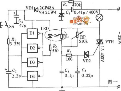
The diagram illustrates a lamp dimmer that gradually increases and decreases light intensity. This feature prevents sudden illumination, which can be a shock to the human eye, and also minimizes damage caused by inrush current when the lamp is...
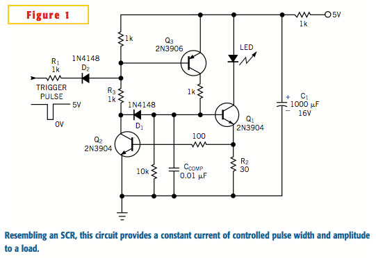
A typical silicon-controlled rectifier (SCR) requires a trigger current to latch on. Once the device is latched, the current flowing through the SCR is determined only by the external component values. The SCR lacks the ability to limit current...
This project will explain the function of a simple RF field meter. The unit will be in great help to tune transmitters for best performances. At the bottom left corner you will see a voltage divider. This divider is...
A circuit breaker is an electronic device that functions to protect an electrical circuit from hazards or damage caused by overloads or short circuits. A circuit breaker operates by automatically interrupting the flow of electricity when it detects an...
The figure illustrates a schematic for an oscillator amplitude-control servo system. The circuit establishes a closed-loop system that provides a fixed and adjustable peak-to-peak amplitude AC signal centered around 0 V. A 1 kHz sine wave, designated as AC_INPUT,...