
LED Lamp Dimmer Circuit Schematic Diagram
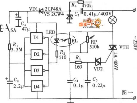
The lamp dimmer circuit is designed to provide a smooth transition in lighting, which is particularly beneficial in environments where abrupt changes in brightness could cause discomfort or visual strain. The core component of the circuit is the optocoupler, which serves to isolate the control signal from the high-voltage side of the circuit, ensuring safety and reliability.
The six inverter circuits are arranged to form a robust driver that can handle varying loads efficiently. The use of four inverters in parallel enhances the circuit's ability to drive higher currents, making it suitable for a range of LED lamp applications. This configuration allows for better thermal management and reduces the risk of overheating, which is critical in maintaining the longevity of LED components.
In operation, the dimmer circuit adjusts the duty cycle of the output signal, effectively controlling the power delivered to the LED lamp. By varying the time the LEDs are turned on and off, the perceived brightness can be modulated smoothly. This method is particularly effective for LED lamps, as it allows for energy savings and extends the lifespan of the lighting system.
Overall, this lamp dimmer circuit not only improves user comfort by providing adjustable lighting but also enhances the performance and durability of LED lamps through its innovative design.The diagram is lamp dimmer which has the function of light gradually, gradually eliminate. It does not appear the light stimulation of the human eye when the lights suddenly illuminated, and also can reduce the damage when open lamp impact current to the bulb, circuit is shown in the diagram. This circuit is LED driver circuit in optocoupler whic h consists of a six inverter circuit, in order to add the driver ability of the circuit, four inverters are use in parallel. You are reading the Circuits of LED Lamp Dimmer Circuit And this circuit permalink url it is 🔗 External reference
Related Circuits
This device is a simple timer that keeps the headlights of a vehicle on for approximately 1 minute and 30 seconds, allowing access to dark areas without the need to manually switch off the lights. Activating switch P1 initiates...
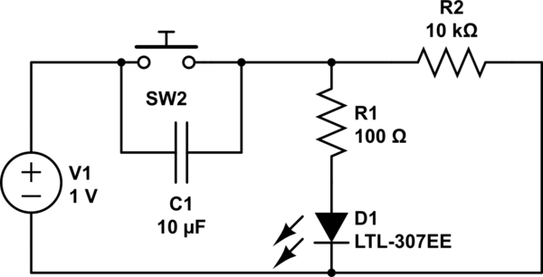
Understand why the LED does not light up, as the capacitor appears to be bypassing the switch. When the capacitor is fully charged, it does not conduct electricity. Although the individual is a beginner, after 20 hours of studying...
This is a simple flyback tester circuit designed to test high-frequency transformers, such as those used in switch-mode power supplies (SMPS) or flyback transformers. The circuit operates as an astable multivibrator with a frequency of approximately 90 kHz, powered...
This is a directly coupled (DC) amplifier circuit. It is constructed using NPN and PNP transistors and is designed to amplify direct current (DC) signals. The directly coupled amplifier circuit utilizes both NPN and PNP transistors to achieve its amplification....
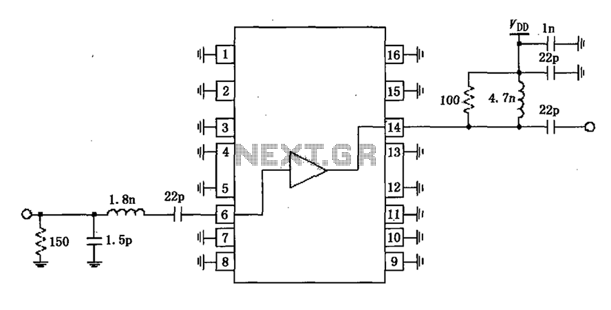
A narrowband linear amplifier circuit configured with the RF2320 operates within a frequency range of 1930 to 1990 MHz. The radio frequency (RF) signal is input from a distance of 6 feet and is amplified by an internal amplifier...
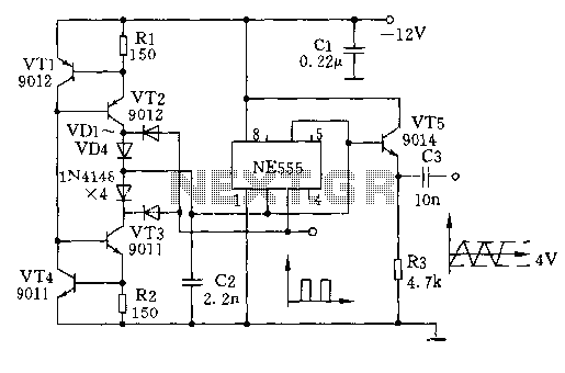
The circuit depicted involves transistors VT1, VT2, and resistor R1, which form a constant current source for charging capacitor C2 in a linear manner. Transistors VT3, VT4, and resistor R2 create a constant current source for discharging capacitor C2,...