
pololu high current motor driver

The Pololu High Current Motor Driver Board is designed for high-performance applications requiring precise control of larger motors. Its compact design integrates essential components for efficient operation, making it suitable for various projects. The board's layout facilitates straightforward connections, with clearly defined positions for power supply, motor, and control interfaces.
The control mechanism utilizes a standard H-Bridge configuration, allowing for bi-directional motor control. The INA and INB pins provide the capability to reverse motor direction, while the PWM input allows for speed modulation through pulse-width modulation techniques. This versatility makes the board ideal for robotics and automation applications where precise motor control is crucial.
Thermal management is a critical aspect of the design, as the VNH2SP30 chip is sensitive to overheating. The recommendation to operate at 14 A continuous is a safety measure to ensure reliability and longevity of the device. The inclusion of a heat sink is advisable for applications that may demand higher current outputs, ensuring that the chip remains within safe operating temperatures.
The reverse-battery protection feature enhances the reliability of the motor driver, safeguarding it against accidental miswiring. However, users should be mindful of the slight increase in resistance and the voltage limitations imposed by this feature.
Overall, the Pololu High Current Motor Driver Board 14A 6V-16V represents a robust solution for controlling high-current motors, combining ease of use, safety features, and the ability to handle demanding applications.Need more current If you`ve got a larger motor waiting to be used, the Pololu High Current Motor Driver Board 14A 6V-16V is just what you need. Connect three digital lines to your microcontroller (five if you want error condition feedback), and you`re ready to go!
The Pololu High Current motor driver board is a compact solution for using the VNH2SP30 motor driver integrated circuit. The board incorporates most of the components of the typical application diagram on page 7 of the VNH2SP30 datasheet, including pull-up and current-limiting resistors and a FET for reverse battery protection. All you need to add is a microcontroller or other control circuit to turn the H-Bridge on and off. In a typical application, the motor power supply is connected at the bottom of the board, the motor on the right side of the board, and the control connections to the left side of the board.
The diagnostic pins can be left disconnected if you do not want to monitor the fault conditions of the motor driver chip. INA and INB control the direction of the motor, and the PWM pin turns the motor on or off. The motor driver has a maximum current rating of 30 A continuous. However, the chip by itself will overheat at much lower currents. That is why it is suggested that you use it at 14A continuous. The actual current you can deliver will depend on how well you can keep the motor driver cool. In our tests, we were able to deliver short durations (on the order of milliseconds) of 30 A and a few seconds of 20 A without overheating.
At 14 A, the chip gets just barely noticeably warm to the touch. For higher currents, a heat sink will be necessary. The motor and power supply wires should also be soldered directly instead of going through the terminal blocks, which are rated for up to 15 A. Manymotor controllers or speed controllers can have peak current ratings that are substantially higher than the continuous current rating; this is not the case with the VNH2SP30, which has a 30 A continuous rating and a over-current protection that can kick in as low as 30 A (45 A typical).
Therefore, the stall current of your motor should not be more than 30 A. (Even if you expect to run at a much lower average current, the motor can still draw high currents when it is starting or if you use low duty cycle PWM to keep the average current down. ) The motor driver board includes an N-channel MOSFET for reverse-battery protection. This component keeps the motor driver from destroying itself if the input power is accidentally connected backwards.
However, this component does slightly increase the total resistance between your battery and your motor, and it limits the operating voltage to a maximum of 20 V. For slightly improved performance or for higher-voltage applications, the MOSFET can be bypassed by connecting the negative battery terminal to the bypass pin.
(This terminal will also need to be connected to your logic supply ground. ) 🔗 External reference
Related Circuits
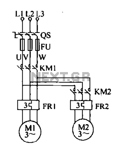
Delay starting a motor control circuit The motor control circuit designed for delayed activation incorporates a timing mechanism that ensures the motor does not start immediately upon receiving power. This is particularly useful in applications where a staggered startup...
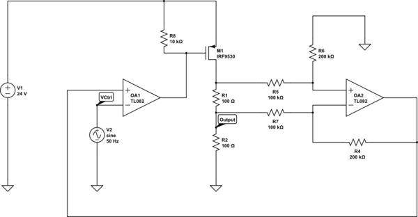
Create a 0-25 mA current limiter using a control voltage input of 0-5 V to regulate the current through a resistive load (R2), which can vary between 0-200 ohms. The O2 operational amplifier (op-amp) functions as a differential amplifier...
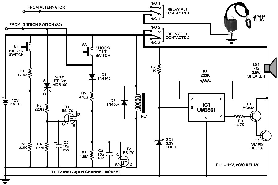
This is a cost-effective motorcycle alarm circuit. During parking, a hidden switch S1 remains normally open, preventing the triggering of MOSFET T1. When the motorcycle is started using ignition switch S2, MOSFET T2 is activated through diode D1 and...
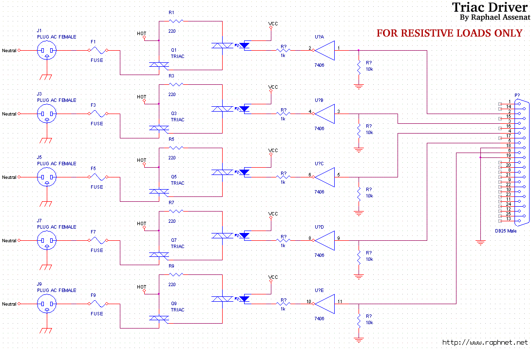
Controlling room lighting using a computer. Triacs and opto-couplers have been purchased for this purpose. A schematic was drawn and a prototype was built, which functioned correctly. Although not visible in the pictures, there is a cable extending from...
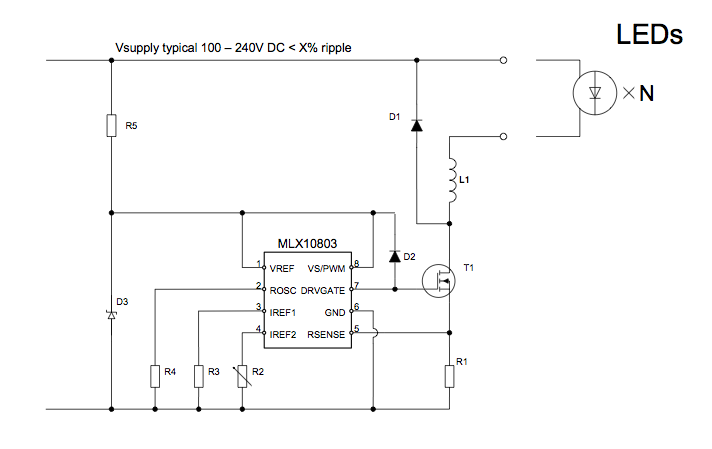
The applications outlined in this document pertain to driving high-power LED diodes. The circuits described can also be utilized in other applications with similar requirements, as long as they adhere to the specifications of the MLX10803. This is a...

A high-input-resistance operational amplifier (op-amp), a bridge rectifier, a microammeter, and several discrete components are necessary to implement this versatile circuit. This circuit can measure DC, AC RMS, AC peak, or AC peak-to-peak voltage by simply altering the resistor...