
Simple DC to 20 MHz Driver
The circuit design focuses on creating a high-performance amplifier capable of handling frequencies up to 20 MHz, with specific requirements including high input impedance, low output impedance, wide bandwidth, and substantial output voltage swing. To achieve the high input impedance necessary to avoid loading the output of the MAX038 function generator, a differential pair of 2N3904 transistors is employed. This configuration allows for effective differential amplification, with the collector currents being processed by a 2N3906 transistor. The 2N3906 is configured with a 1kΩ collector load connected to -5V through a bias network, which helps maintain the necessary conditions for the complementary pair and buffers the high impedance collector of the second amplifier stage.
The choice of resistor values is critical; lower resistance values are selected to ensure sufficient output current for a wide output range exceeding 5V (-2.6V to +2.6V) while driving terminations. This approach also ensures that the transistors operate within their bandwidth limits, preventing capacitive effects from causing premature roll-off at higher frequencies.
Stabilization of the amplifier is addressed by considering the phase shift introduced by the three-stage design. At certain frequencies, a 180-degree phase shift can occur between the inverting input and the output, potentially leading to instability. Traditional dominant pole compensation is not viable due to insufficient excess gain; therefore, a broad bandwidth network is employed to shunt the amplifier's input, effectively reducing loop gain. This is accomplished using a 0.1µF capacitor in series with a 100Ω potentiometer, which is connected between the two inputs of the first stage.
Setting the potentiometer to approximately 50Ω, combined with the impedance of the two 1kΩ resistors that configure the closed-loop gain at 500Ω, results in a loop gain reduction of about 40dB at frequencies above the corner frequency of the capacitor and the 50Ω resistor (approximately 30 kHz). This configuration ensures that the gain remains below 0dB at 80 MHz, where the amplifier is prone to oscillation. The use of a potentiometer allows for precise adjustments to achieve optimal square wave response, which would be more challenging with fixed resistors.The output cable from my 20 MHz function/sweep generator dangled over the side of the workbench, the alligator clip hovering over the floor. Deeply engrossed in a project, I moved the power strip on the floor a little closer so I could plug in the circuit upon which I was working.
That's when the alligator clip contacted the 240 VAC. The function/sweep generator had been gravely injured. Poking around with a scope probe, the signal output was down in the noise, but it was there, and the other outputs worked. The expensive, rare, and discontinued MAX038 function generator chip was still working. Upon opening the case, I found that the Ztex ZXFY202N8 wide band opamp had been destroyed and the output termination resistor burnt and broken.
I replaced the ZXFY202N8 with the spare I had stored inside the funciton/sweep generator but something was not connected correctly. The opamp is wired into the circuit point-to-point on the back of the circuit board. After a several cycles of removing the circuit board, touching up suspect solder joints, and reinstalling the board, I gave up and decided to build another amplifier on the benchtop where I could more easily troubleshoot it.
I am out of the ZXFY202N8 opamps. There is noting like that available in the electronics and surplus stores here, and my mail order supplier's web site did not have anything that is even close. But I have a lot of very fast transistors. It quickly became apparent that the old reliable 2N3904 and 2N3906 transistors would be plenty fast, had sufficient gain, and were not exotic at all.
It took a couple of hours to put the amplifier together and debug it. That activity was much more enjoyable than going through the uninstall-troubleshoot-install cycles. Circuit Description The circuit had some apparently tough constraints: High input impedance so as to not load down the output of the MAX038, a low impedance output to drive the coax and any loads, wide bandwidth -as flat as I could get to at least 20 Mhz, and a full bandwidth output voltage swing to within 2.5 volts of the power supply rails. For the high input impedance the circuit uses a differential pair of 2N3904 transistors. The collector currents are differentially amplified by a 2N3906, which has its 1k collector load connected to - 5 volts though a bias network for the complementary pair buffers the high impedance collector of the second amplifier stage to drive the output termination resistor.
The relatively low values of the resistors are needed to allow sufficient output current to provide the large output range of over 5 volts (- 2.6 volts to + 2.6 volts) while driving terminations, to keep sufficient current through the transistors for them to have adequate bandwidth and so that capacitances don't cause the amplifier stages to roll off at frequencies that are too low. Once the bandwidth and load driving signal swing were confirmed, the next problem was how to stabilize the amplifier.
Having three stages means that at some frequency, there is 180 degrees phase shift between the inverting input and the output. Dominant pole compensation would not work because there was not enough excess gain in the circuit. That left me with the trick of shunting the amplifier's input with a broad band network to reduce the loop gain.
That is the purpose of the 0.1 uf capacitor in series with the 100 ohm pot. The 0.1 uf capacitor and 100 ohm pot is connected between the an input stage's two inputs. The pot is set to about 50 ohms and the impedance of the two 1k resistors that set the closed loop ;gain is 500 ohms, which results in the loop gain being lowered by about 40 db at frequencies above the corner frequency of the 0.1uf capacitor and the 50 ohm resistor (about 30 kHz), which is enough to keep the gain at 80 Mhz, where the amplifier tended to oscillate, less than 0 db. I tried using a fixed resistor, but I noticed that to get excellent square wave response, the loop gain had to be critically adjusted.
Using a pot was much easier than selecting a set of resistors. 🔗 External reference
Related Circuits
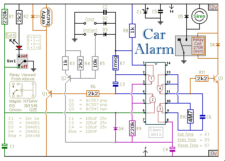
This circuit includes automatic exit and entry delays, an optional instant alarm zone, an optional intermittent siren output, and an automatic reset feature. By incorporating external relays, it is possible to immobilize the vehicle and activate the lights. For...
Having found a u664b prescaler chip (Telefunken) from an old TV tuner, I decided to build a valid frequency counter using PIC16F84. The prescaler I use is able to divide by 64 every frequency from 30 to 1300 MHz....
Manufacturers are beginning to utilize new high-power white-light LEDs to provide a photoflash function suitable for low-light conditions. These LEDs produce... High-power white-light LEDs have emerged as a significant advancement in lighting technology, particularly for applications requiring enhanced illumination in...
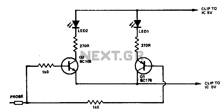
If the probe is connected to logic 0, Q1 will be activated, illuminating D1. When connected to logic 1, Q2 will be activated, illuminating D2. Any NPN or PNP transistors can be used for Q1 and Q2. Likewise, D1...
A simple network design is a key feature of the Pierce circuit, as illustrated by these 1-MHz oscillators. Operating the crystal slightly above resonance requires only one high-gain transistor stage. Operating it exactly at series resonance requires an additional...
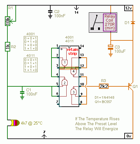
A CMOS 4001 or a CMOS 4011 can be utilized in this circuit, as both contain four two-input gates. The inputs of each gate are connected together, allowing them to function as simple inverters. This means that when both...
Warning: include(partials/cookie-banner.php): Failed to open stream: Permission denied in /var/www/html/nextgr/view-circuit.php on line 713
Warning: include(): Failed opening 'partials/cookie-banner.php' for inclusion (include_path='.:/usr/share/php') in /var/www/html/nextgr/view-circuit.php on line 713