
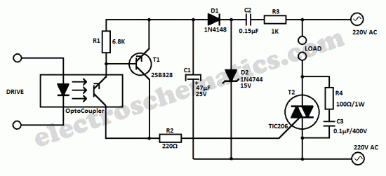
triac for this light dimmer circuit
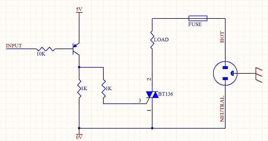
The circuit aims to control the brightness of a light source through phase control using a silicon-controlled rectifier (SCR) and an optocoupler for isolation and triggering. The BT136 is a popular choice for light dimming applications due to its ability to handle significant power levels. It is a three-terminal device that requires a gate trigger to turn on and will remain on as long as the current through it exceeds a certain threshold.
The MOC3022 optocoupler plays a crucial role in providing electrical isolation between the control circuit and the high-voltage AC load. It consists of an LED and a phototransistor. When the LED is activated, it emits light that activates the phototransistor, allowing current to flow and triggering the gate of the BT136 SCR.
To ensure proper operation of the circuit, the following aspects should be examined:
1. **Component Ratings**: Verify that the BT136 and MOC3022 are rated for the voltage and current levels of the application. The SCR should be able to handle the peak voltage and current of the load.
2. **Triggering Circuit**: Ensure that the circuit designed to trigger the gate of the BT136 is functioning correctly. This may involve checking the resistor values, ensuring proper isolation, and confirming that the optocoupler is receiving adequate input.
3. **Phase Control Timing**: The timing of the triggering signal is critical for dimming functionality. The phase control method requires precise timing to adjust the point in the AC cycle at which the SCR is triggered, thus controlling the amount of power delivered to the load.
4. **Load Compatibility**: Confirm that the load (e.g., incandescent bulb) is compatible with dimming. Certain types of lights, such as LED or fluorescent bulbs, may require specific dimming circuits or additional components to function correctly.
By addressing these components and ensuring that all connections are secure and correctly configured, the circuit can be made operational. If issues persist, further troubleshooting may be necessary to identify any faulty components or design flaws.Hi all I made this circuit to be a light dimmer but it did not work. I use BT136 for the SCR and MOC3022 for optocoupler. Can you tell me what is the.. 🔗 External reference
Related Circuits
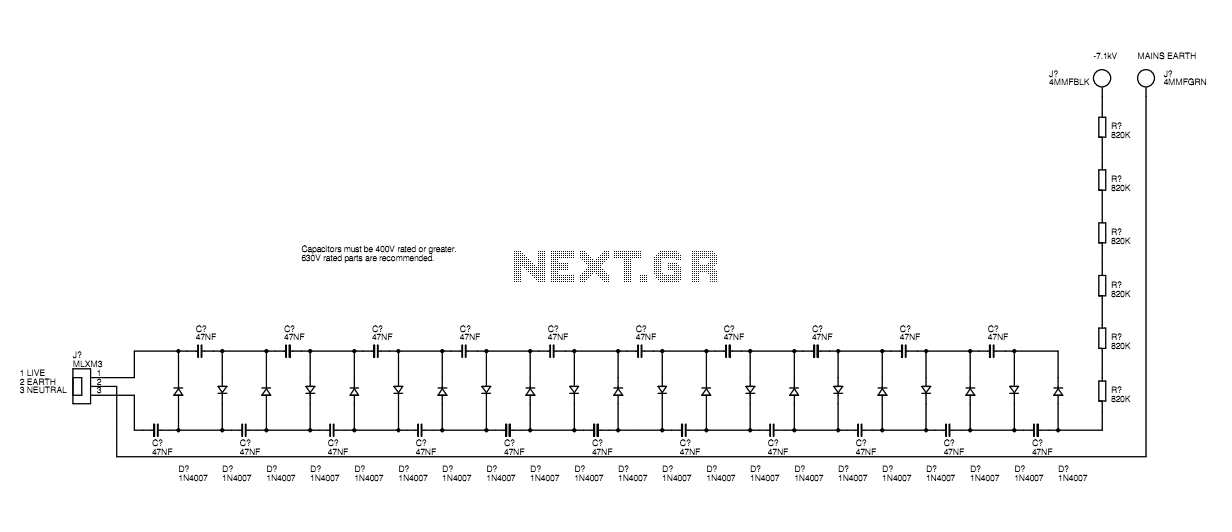
A basic mains driven Cockroft ladder high voltage generator is shown in the schematic. This is functionally the same as a project in Electronics Today International many years ago. The peak mains voltage of 340V appears across each capacitor...
The Mark3 version of the Infrared extender is specifically designed to control appliances that utilize high-frequency modulated infrared remote signals. The Mark3 Infrared extender functions as a bridge between a standard infrared remote control and appliances that operate with high-frequency...
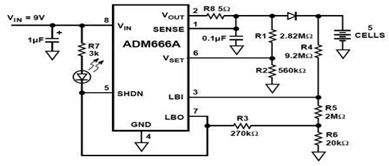
The ADM666A application note provides a detailed explanation of a low-cost battery charger circuit, including maximum output voltage, charge termination voltage calculation, battery voltage level monitoring, and circuit efficiency optimization. The ADM666A utilizes an NPN transistor and a P-channel...
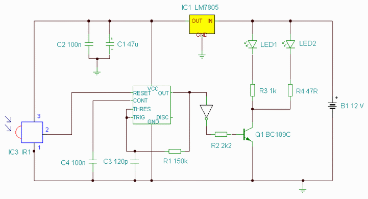
The finger, positioned within a light screen, is situated between a high-intensity LED emitter and a photocell. It generates a heartbeat signal that, when appropriately amplified, serves as the input for a PIC16F84 microcontroller. The microcontroller drives three common...
This universal triac controller circuit with optocoupler addresses the issue that triacs face when operating at low temperatures, as they require a higher gate trigger voltage. The universal triac controller circuit is designed to enhance the performance of triacs, particularly...
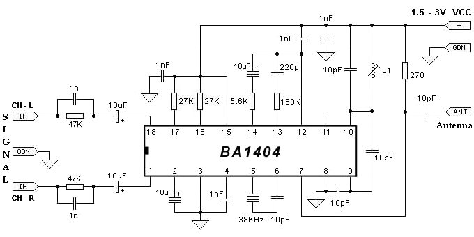
The BA1404 FM stereo modulator IC includes all the necessary components to design a simple, high-efficiency stereo transmitter circuit. It features a stereo modulator that generates composite stereo signals, an FM modulator for creating FM signals, and an RF...