
Voltage to Frequency Converter Circuit
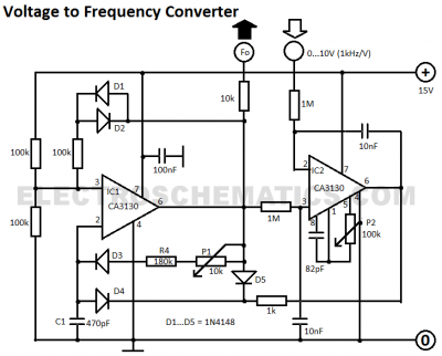
The voltage-to-frequency converter circuit is designed to convert an input voltage into a corresponding frequency output. The core of this circuit is a voltage-controlled oscillator (VCO), which generates a frequency that varies with the input voltage. The precision of this circuit is highlighted by the low deviation of 0.5%, ensuring that the output frequency closely tracks the input voltage.
IC1, serving as the multivibrator, is typically configured to produce a square wave output. In this application, it is used to establish the oscillation frequency based on the control voltage applied to it. The multivibrator configuration can be either astable or monostable, depending on the desired output characteristics. In an astable configuration, the circuit continuously oscillates between two states, while in a monostable configuration, it generates a pulse in response to a triggering event.
Additional components may include resistors and capacitors that set the timing characteristics of the multivibrator, influencing the frequency range and stability of the output signal. The design may also incorporate feedback mechanisms to enhance linearity and minimize distortion in the frequency output.
This voltage-to-frequency converter can be utilized in various applications, including analog-to-digital conversion, frequency modulation, and signal processing, where precise frequency control is essential. The circuit's performance can be further optimized by selecting appropriate passive components and ensuring the power supply is stable, as variations in supply voltage can affect the VCO's output frequency.This voltage to frequency converter circuit has an oscillator that is voltage controlled and has a small, 0.5% deviation. IC1 function as a multivibrator a. 🔗 External reference
Related Circuits
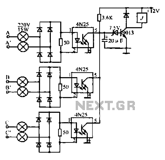
A, B, and C are used for a large power split-phase system. The A + BC range generator phase line features an A-A indole path string containing two 220V/15W bulbs. The bulbs recover based on macro instructions from J...
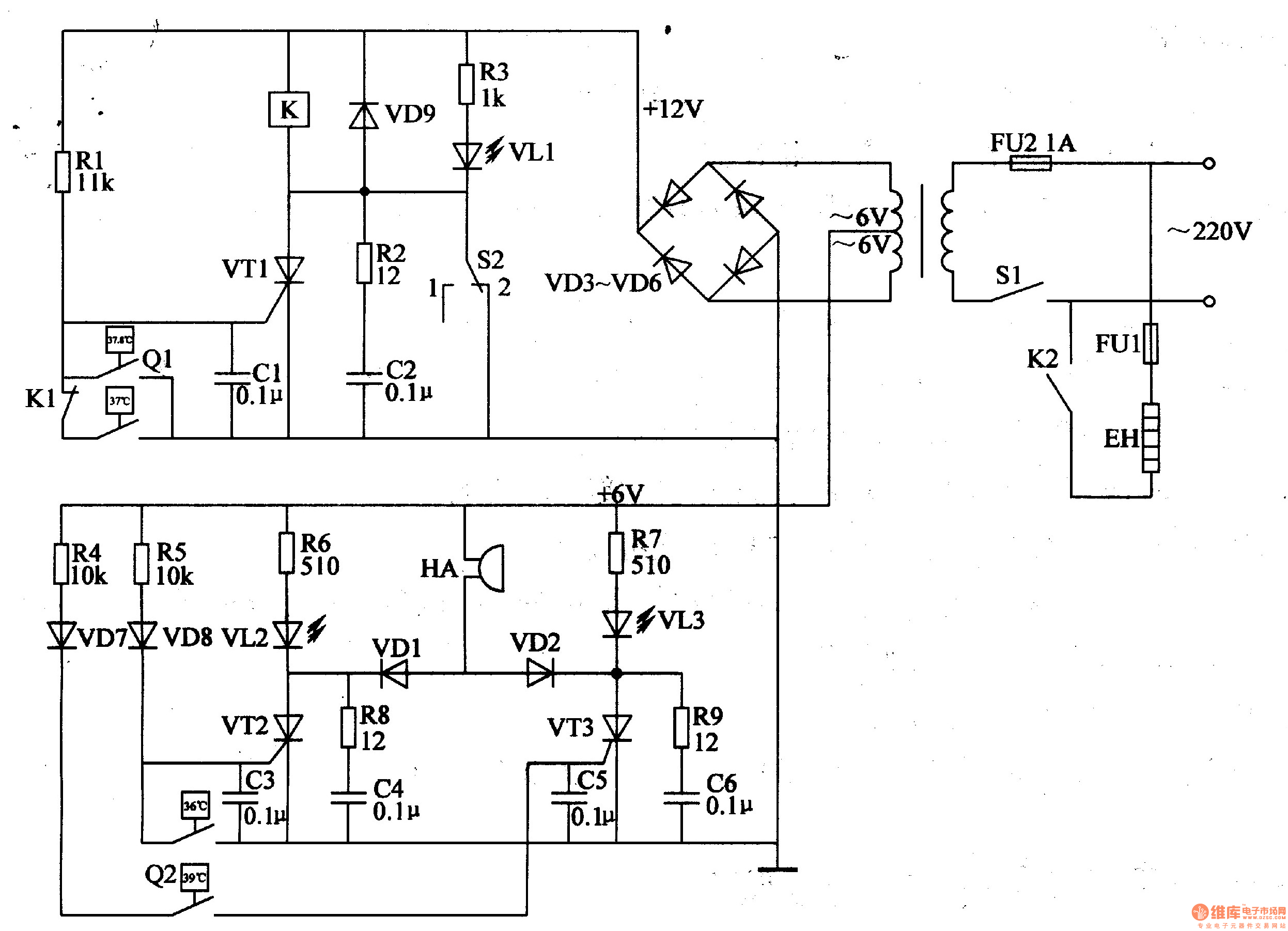
The egg hatching incubator circuit comprises a power supply circuit, a constant temperature control circuit, and a sound and light alarm circuit, as illustrated in Figure 4-7. The power supply circuit includes a power switch (S1), a fuse (FU2),...
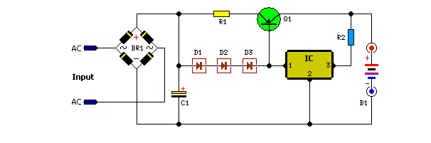
Unlike many units, this battery charger continuously charges at maximum current, tapering off only near full battery voltage. In this unit, the full load. This battery charger is designed to operate with a continuous charging mechanism, maintaining the maximum current...
The figure illustrates a simple project schematic of a metronome. A metronome is a device utilized by musicians to produce continuous beats through a speaker. The metronome circuit typically consists of several key components that work together to generate a...
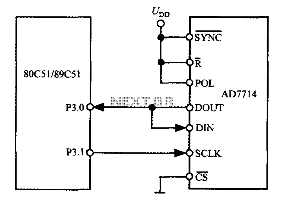
The 3-wire interface to the AD7714 can be utilized with various microcontrollers, including microcontrollers and microprocessors. This 3-wire serial interface is particularly suitable for isolation systems, allowing the use of optical couplers. The interface circuit between the AD7714 and...
This circuit functions as a camera switch, allowing multiple cameras to be connected to a single monitor. It can operate in both manual and automatic modes. In automatic mode, the circuit utilizes a 555 astable multivibrator to generate a...