Simple Door Alarm Project

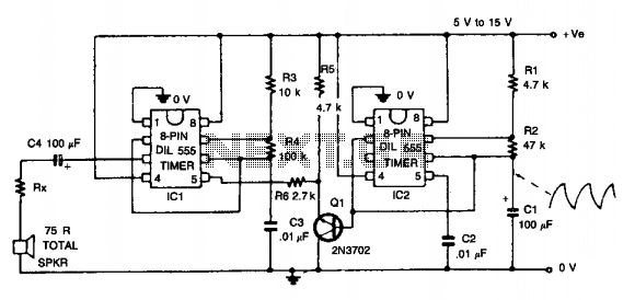
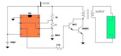
Simple Burglar Alarm / Door Alarm Circuit Diagram. This project can be utilized to secure a door or window. It emits a loud beep and activates the room light when an intruder attempts to break the door lock.
The Simple Burglar Alarm circuit is designed to provide a basic security solution for doors and windows. It typically consists of a few key components: a switch (often a reed switch or a push button), a sound-producing device (like a buzzer or speaker), a light source (such as an LED or a small lamp), and a power supply (usually a battery).
When the circuit is armed, the switch remains closed. If an intruder attempts to open the door or window, the switch opens, triggering the buzzer to sound an alarm. This loud beep serves as both a deterrent to the intruder and a notification to anyone nearby. In addition to the sound alarm, the circuit can be designed to activate a light source, enhancing visibility and drawing attention to the situation.
The power supply, typically a 9V battery, provides the necessary voltage to operate the components. Resistors may be included in the circuit to limit the current to the LED and protect it from damage. A transistor can be used to amplify the signal from the switch to drive the buzzer and light, ensuring they operate effectively.
The schematic would clearly depict the connections between these components: the switch would be connected in series with the buzzer and the light, while the power supply would provide the necessary voltage. Proper placement of components and wiring is crucial for the circuit to function as intended.
Overall, this simple burglar alarm circuit is an effective way to enhance security in residential or commercial settings, providing immediate feedback in the event of unauthorized access.Simple Burglar Alarm / Door Alarm Circuit Diagram. You can use this Simple project to protect the door or Window. It gives a loud beep and switch on the room light when an intruder attempts to breaks the door lock 🔗 External reference
Warning: include(partials/cookie-banner.php): Failed to open stream: Permission denied in /var/www/html/nextgr/view-circuit.php on line 713
Warning: include(): Failed opening 'partials/cookie-banner.php' for inclusion (include_path='.:/usr/share/php') in /var/www/html/nextgr/view-circuit.php on line 713


