
cmos 4060 burglar alarm
This single-zone alarm system is designed to provide comprehensive security for a designated area. The automatic exit, entry, and siren cut-off timers enhance user convenience and system reliability. The ability to accommodate various normally-closed input devices allows for flexibility in installation and use, making it suitable for different security applications.
The circuit operates within a voltage range of 5 to 15 volts, which allows for compatibility with common power supplies. The choice of a siren, buzzer, and relay tailored to the selected voltage ensures that users can customize the system to meet specific requirements. The exit delay feature, indicated by the eight beeps, is crucial for allowing users to exit the premises without triggering the alarm. The adjustable resistor R6 provides versatility in setting the exit delay, which can be tailored to individual preferences or security needs.
The confirmation mechanism that the loop is intact, indicated by the cessation of the buzzer after the exit delay, is an essential feature. It alerts users to any potential security breaches, ensuring that they can address any open points before leaving the premises. The entry delay, which mirrors the exit delay but is indicated by a continuous beep, provides a clear auditory signal that alerts users while they re-enter the secured area.
The siren cut-off timer, which is significantly longer than the exit delay, ensures that in the event of an alarm activation, the siren provides a prolonged alert to deter unauthorized access. The continued sounding of the buzzer after the siren has stopped serves as a reminder of the alarm's activation status, prompting users to investigate.
The inclusion of diode D10, while optional, enhances the functionality of the system by ensuring that the buzzer remains active during critical phases of the alarm cycle. This feature can be particularly useful in environments where audible alerts are necessary for user awareness.
The circuit's design also incorporates protective measures for components such as the electrolytic capacitor. The presence of resistor R5 mitigates the risk of capacitor failure due to incorrect polarity, while the recommendation for a non-polarized capacitor ensures that the oscillator operates reliably. The innovative solution of connecting two polarized capacitors back-to-back to simulate a non-polarized capacitor demonstrates a practical approach to circuit design, ensuring both functionality and reliability.
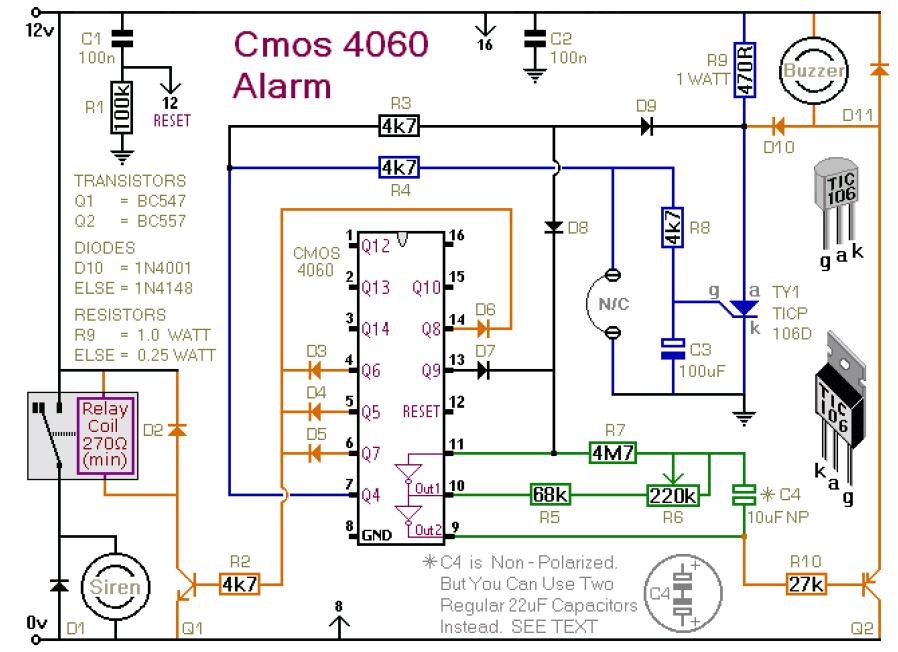
Overall, this single-zone alarm system offers a robust and flexible solution for enhancing security, with features designed to accommodate user needs and protect critical components effectively.This is a single zone alarm - with automatic exit, entry and siren cut-off timers. It will accommodate all the usual types of normally-closed input devices - such as magnetic-reed contacts - foil tape - PIRs etc. I`ve used a 12-volt supply in the drawing - but the circuit will work at anything from 5 to 15-volts.
All you need do is select a siren, buzzer, and relay to suit the voltage you`re using. When you switch the alarm on - the buzzer will sound eight times. This is the exit delay. Before the end of the eighth beep - you can leave the building without activating the alarm. R6 controls the length and speed of the beeps. It can be adjusted to give an exit delay of anything from about ten seconds - up to about a minute. After the eighth beep - the buzzer should stop sounding. This confirms that the loop has been restored within the time allowed. If the buzzer does not stop - but changes instead to a continuous beep - the loop is open and the building isn`t secure. When this happens - you should switch off the alarm - and check for open doors, windows etc. When you return and open the door - the buzzer will sound again - and the entry delay will start. The entry delay is the same length as the exit delay. But to distinguish it from the exit delay - the buzzer will sound continuously. If the buzzer is sounding continuously - the alarm has been activated - and the entry delay has begun.
If you don`t switch the alarm off before the entry delay expires - the siren will sound. The siren will sound only once. Just as R6 sets the lengths of the exit and entry delays - it also sets the siren cutoff time. The siren cut-off delay is 30 times the length of the exit delay. With the exit delay set at 30-seconds - the siren will sound for about 15-minutes. Then it will switch off - and remain off. After the cut-off timer has switched the siren off - the buzzer will continue to sound. So when you return - if the buzzer is sounding - you`ll know that the alarm has been activated. Note that D10 is optional. Its job is to sound the buzzer constantly during the entry delay. It`s also responsible for keeping the buzzer going after the siren has stopped. If you leave out D10 - the buzzer will beep eight times during both the exit and entry delays. And - when the siren cuts-off - the buzzer will cut off also. A regular electrolytic capacitor is polarised. If the charge on its plates is the wrong way round - DC current will flow through the capacitor. If the current is high enough - the capacitor will heat up and explode. The presence of R5 in the circuit means that this is not going to happen. But if you use a polarised capacitor - it may mean that the oscillator won`t run - or won`t run reliably. While the oscillator is running - the polarity of the charge on C4 keeps reversing. So C4 needs to be nonpolarised. However - you can simulate a non-polarised 10uF capacitor by connecting two 22uF polarised capacitors back to back - as shown.
🔗 External reference
Related Circuits
This schematic is simple and easy to construct. The integrated circuit (IC) generates all the sound effects, with the output at Pin 3 being amplified by a transistor. A 64-ohm loudspeaker can be used instead of the 56-ohm resistor...
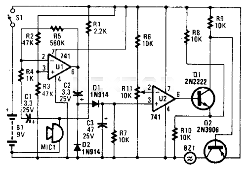
In the circuit, U1 amplifies the audio captured by the condenser microphone. Resistor R1 limits the current, while R2 and R3 center the amplifier's output to a voltage level of %B+ to facilitate the use of a single-ended power...
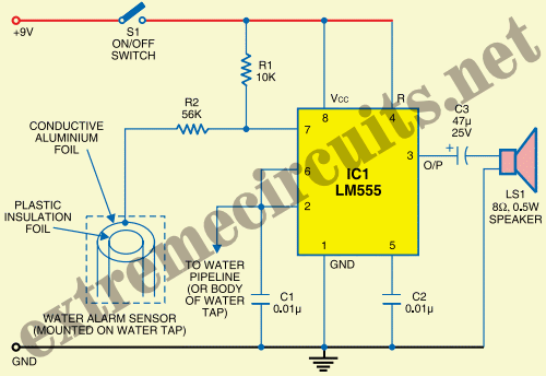
The State Jal Boards provide water for a limited duration each day. The timing of water supply is determined by the management, and the public is not informed of this schedule. The operation of State Jal Boards typically involves a...
Most of the power supply failure indicator circuits need a separate power supply for themselves. But the alarm circuit presented here needs no additional supply source. It employs an electrolytic capacitor to store adequate charge, to feed power to...
Over-Temperature Alarm Circuit Uses Common, Inexpensive Components | Negative-temperature-coefficient (NTC) thermistor, ICs. The Over-Temperature Alarm Circuit is designed to detect excessive temperatures and provide an alert using readily available and cost-effective components. The core sensing element of this circuit is...
This circuit warns the user against fire accidents. It relies on the smoke that is produced in the event of a fire. When this smoke passes between a bulb and an LDR, the amount of light falling on the...
Warning: include(partials/cookie-banner.php): Failed to open stream: Permission denied in /var/www/html/nextgr/view-circuit.php on line 713
Warning: include(): Failed opening 'partials/cookie-banner.php' for inclusion (include_path='.:/usr/share/php') in /var/www/html/nextgr/view-circuit.php on line 713