
Constituting simple LM3915 audio power meter circuit
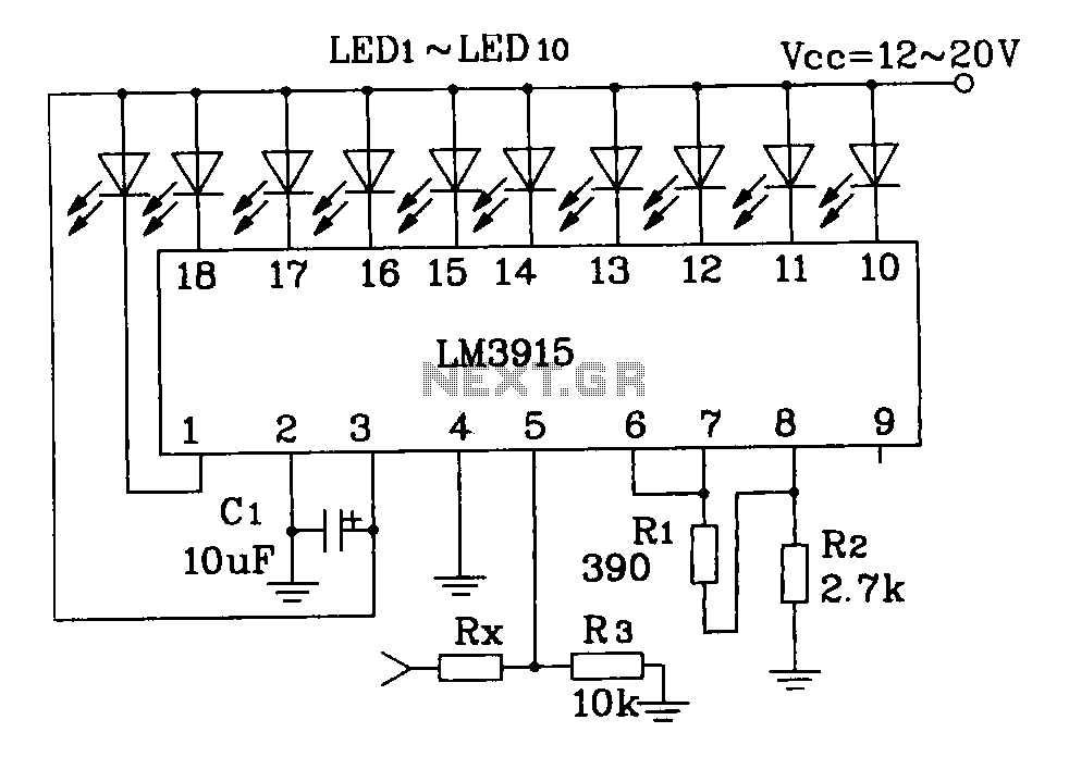
The LM3915 is a versatile LED bar graph/LED dot display driver that can be utilized to create an audio power meter. The circuit typically consists of the LM3915 IC, a set of LEDs for visual output, and resistors to set the input impedance based on the connected speaker's internal resistance.
For a 4-ohm speaker, the use of a 10k ohm resistor for Rx ensures that the circuit is appropriately calibrated to display the audio power accurately. When dealing with an 8-ohm speaker, increasing Rx to 18k ohms compensates for the higher resistance, maintaining the circuit's sensitivity and accuracy. Similarly, for a 16-ohm speaker, a 30k ohm resistor is necessary to ensure proper functionality.
The implementation of a half-wave AC signal converter is an advanced technique that enhances the performance of the audio power meter. This converter rectifies the AC signal, producing a DC signal that can be processed by the LM3915. By converting the AC input signal into a DC format, the circuit can provide a more stable and reliable output, allowing for precise visual representation of audio power levels.
In summary, the LM3915 audio power meter circuit can be effectively tailored to various speaker impedances by adjusting the resistor values. The addition of a half-wave AC signal converter further refines the circuit's performance, enabling it to accurately reflect audio power levels through a visual output.Constituting simple LM3915 audio power meter circuit diagram Note: If the internal resistance of 4 speaker when, Rx take 10k If the internal resistance 8 speaker when, Rx take 18k speaker if the internal resistance 16 when, Rx take 30k Levin show a use of such IC AC input signal amplitude more sophisticated method is to use a half-wave AC signal converter will be changed to a DC signal, and then the DC signal is then fed to the input of the IC.
Related Circuits
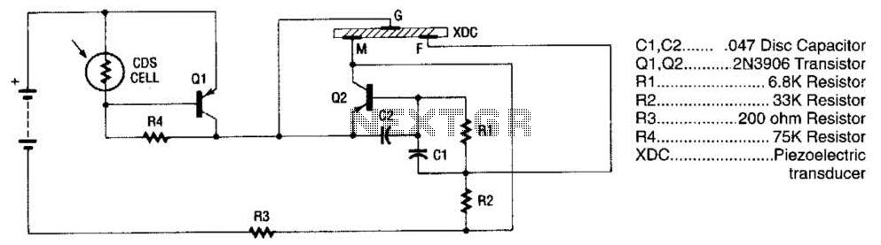
The alarm utilizes a fixed-frequency piezoelectric buzzer alongside a cadmium-sulfide (CDS) cell and a two-transistor circuit to create a distinctive effect. When light reaches the CDS photoelectric cell, the alarm remains silent. However, in the absence of light, transistor...

The sensor must be positioned at an angle of approximately 30 to 45 degrees relative to the ground. This orientation facilitates the drainage of rainwater, preventing accumulation that could trigger the alarm due to water retention on the sensor....

This circuit is a touch switch circuit, similar to a touch door alarm. It utilizes a 555 timer as the core component of the touch switch circuit. The operation begins when the plate is touched, triggering the 555 timer....
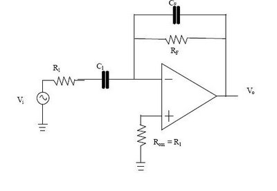
The differentiator circuit is an application circuit derived from mathematical principles influenced by capacitor behavior. The circuit, as illustrated in the accompanying image, is a simple differentiator configuration. To derive the differentiator formula, the following sequence is used: Ic...
A real-time controller is a device designed to continuously manage household devices, both in real-time and according to a predetermined schedule. This article focuses on a series of real-time controllers utilizing the AT89C2051 microcontroller, which serves this purpose effectively....
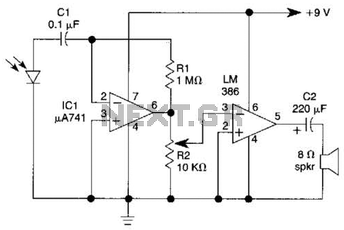
This light-wave receiver comprises a 741 operational amplifier functioning as a preamplifier and an LM386 operational amplifier serving as a power amplifier. The gain control is managed by a potentiometer labeled R2. Various types of detectors can be utilized...
Warning: include(partials/cookie-banner.php): Failed to open stream: Permission denied in /var/www/html/nextgr/view-circuit.php on line 713
Warning: include(): Failed opening 'partials/cookie-banner.php' for inclusion (include_path='.:/usr/share/php') in /var/www/html/nextgr/view-circuit.php on line 713