Simple Electronic Combination Lock circuit diagram
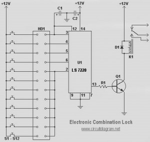
This circuit diagram represents a simple electronic combination lock utilizing the IC LS7220. The circuit is designed to activate a relay for controlling any device (on and off) each time a specific combination of four digits is entered. It can operate within a voltage range of 5V to 12V. To set the combination, connect the appropriate switches to pins 3, 4, 5, and 6 of the IC. For example, if switch S1 is connected to pin 3, S2 to pin 4, S3 to pin 5, and S4 to pin 6 of the IC, the combination will be 1234, allowing for the creation of any four-digit combinations. The remaining switches should be connected to pin 2 of the IC, which will reset the IC if an invalid key is pressed, requiring the entire key code to be re-entered. Upon entering the correct combination, the output (relay) will be activated for a predetermined duration, controlled by capacitor C1, which is set to 6 seconds. Increasing the value of C1 will extend the preset time. For the keypad, arrange the switches in a 3x4 matrix on a printed circuit board (PCB) and label the keys with digits using a marker. To enhance security, symbols can be used instead of numbers, potentially confusing unauthorized users.
The electronic combination lock circuit based on the LS7220 IC is a practical application for controlling access to devices or systems. The LS7220 is a keypad encoder that processes input from a matrix keypad and outputs a unique combination code. The use of a relay allows for the switching of higher power devices, making this circuit suitable for various applications, including home security systems, electronic safes, and automated access control systems.
The circuit consists of a matrix keypad, which typically includes 12 keys arranged in a 3x4 layout. Each key corresponds to a unique input that the LS7220 encodes into a binary format. The connections to pins 3, 4, 5, and 6 of the IC must be carefully planned to ensure the desired combination is correctly interpreted. The reset function, connected to pin 2, is crucial for maintaining security, as it prevents unauthorized access by requiring a complete re-entry of the code after any incorrect input.
Capacitor C1 plays a significant role in the timing aspect of the circuit. The preset time for the relay activation can be adjusted by varying the capacitance value, allowing for customization based on specific requirements. This feature is particularly useful in applications where the duration of access needs to be controlled.
The design of the printed circuit board (PCB) should accommodate the layout of the switches and the IC, ensuring minimal interference and optimal performance. Proper labeling of the keys is essential for user interaction, and using symbols instead of numbers can add an additional layer of security by obscuring the actual combination from potential intruders.
Overall, this electronic combination lock circuit presents an effective solution for controlled access, combining ease of use with customizable security features.This could be the circuit diagram of a easy electronic combination lock by using IC LS 7220. This circuit may be applied to activate a relay for controlling (on & off) any device each time a preset combination of 4 digits are pressed. The circuit may be operated from 5V to 12V. To set the mixture connect the appropriate switches to pin 3, 4, 5 and 6 o f the IC through the header. As an example if S1 is connected to pin 3, S2 to pin 4, S3 to pin 5, S4 to pin 6 of the IC, the combination is going to be 1234. This way we can create any 4 digit combinations. Then connect the rest of the switches to pin 2 of IC. This will cause the IC to reset if any invalid key is pressed, and entire key code has to be re entered.
When the correct key combination is pressed, then the output ( relay) will be activated for a preset time driven by the capacitor C1. Here, it is set to be 6S. Increase the value of C1 to increase the preset time. For the keypad, arrange the switches in a 3X4 matrix on a PCB (Printed Circuit Board). Write the digits on the keys by using a marker. Instead of applying numbers I wrote some symbols!. The bad guys is going to be more confused with this. 🔗 External reference
