
Fast circuit breaker

This electronic circuit breaker is designed for 115 Vac applications, providing efficient overcurrent protection through its adjustable trip point. The TMOS MTM15N50 transistor is a key component, chosen for its low drive power requirements and minimal on-resistance, which contribute to the overall efficiency and responsiveness of the circuit. The full-wave diode bridge configuration, comprising diodes D1 to D4, allows for effective rectification of AC input, ensuring that the circuit breaker operates reliably regardless of the input phase.
The comparator U1 plays a critical role in monitoring the current flowing through the circuit. It compares the voltage drop across resistor R1, which is directly proportional to the current, with a reference voltage derived from the internal battery. The adjustable resistor R6 sets the threshold level for the comparator, allowing for customization of the trip point according to specific application requirements.
When the current exceeds the predetermined threshold, the resulting increase in voltage across R1 triggers the comparator, leading to a low output signal from U1. This signal is used to turn OFF the transistor Q1, effectively opening the circuit and disconnecting the load from the power source. The illumination of the LED fault indicator serves as a visual alert, informing users of the overcurrent condition and the status of the circuit breaker.
The inclusion of zener diodes D6 and D7 provides additional voltage regulation and protection, ensuring that the comparator operates within safe voltage levels. The overall design emphasizes reliability and safety, making it suitable for various applications where overcurrent protection is essential. The integration of battery power not only enhances circuit isolation but also ensures that the circuit breaker remains operational in the event of a power failure, further adding to its robustness and utility in critical systems.This 115 Vac, electronic circuit breaker uses the low drive power, low on resistance and fast turn off of the TMOS MTM15N50. The trip point is adjustable, LED fault indication is provided and battery power provides complete circuit isolation.
The two "circuit breaker" terminals are across one leg of a full wave diode bridge consisting of D1-D4. Normally, Q1 is turned ON so that the circuit breaker looks like a very low resistance. One input to comparator Ul is a fraction of the internal battery voltage and the other input is the drop across zeners D6 and D7 and the voltage drop across R1.
If excessive current is drawn, the voltage drop across Rl increases beyond the comparator threshold (determined by the setting of R6), U1 output goes low, Q1 turns OFF, and the circuit breaker "opens." When this occurs, the LED fault indicator is illuminated. 🔗 External reference
Related Circuits

This circuit was detailed in a recent edition of an amateur radio magazine. It enables operation in the 160 to 190 kHz band with a maximum power output of 1 W (license-free) in various modes such as CW, SSB,...
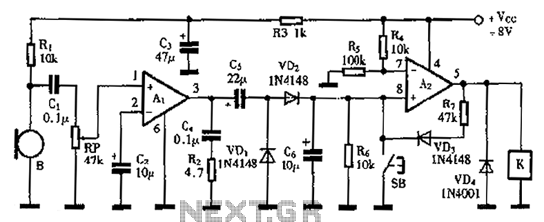
A practical voice-activated switch is presented. An A1 amplifier is connected to a conventional microphone (B) that picks up the audio control signal, which is then amplified. After amplification, the signal passes through components C5, VD1, and VD2, forming...

This compact FM transmitter has a range of approximately 50 meters and is designed for hobbyists. With multiple mini-transmitters, users can create a diverse and engaging radio program. The device achieves high frequency stability due to its power supply...

This circuit is the simplest inductive balancing metal detector (IB, Induction Balance) that can be constructed. The LB metal detection method offers satisfactory depth of penetration and effectively distinguishes between iron-based and noble metallic objects. While several metal detectors...

Metal detectors are typically complex devices that often incorporate expensive components, making DIY metal detector circuits uncommon. However, this metal detector hobby circuit can be built using only a few components, such as a BC548 transistor and a standard...
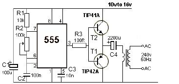
12V power inverter circuit utilizing a 555 timer for an electronic project. The 12V power inverter circuit is designed to convert a DC voltage of 12 volts into an AC voltage suitable for powering small electronic devices. The core component...
Warning: include(partials/cookie-banner.php): Failed to open stream: Permission denied in /var/www/html/nextgr/view-circuit.php on line 713
Warning: include(): Failed opening 'partials/cookie-banner.php' for inclusion (include_path='.:/usr/share/php') in /var/www/html/nextgr/view-circuit.php on line 713