
Simple Electronic Metronome
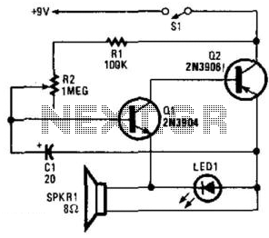
The oscillator circuit utilizes a pair of complementary transistors, typically one NPN and one PNP, configured in a feedback loop to generate oscillations. The transistors are connected in such a way that the output of one transistor is fed back to the base of the other, establishing a regenerative feedback that sustains oscillations. The frequency of oscillation is primarily determined by the values of the resistors and capacitors in the circuit.
In terms of component selection, the transistors should be chosen based on their switching speed and current handling capabilities to ensure reliable operation within the desired frequency range. Resistors are used to set the biasing conditions for the transistors, while capacitors determine the timing characteristics of the oscillation. By adjusting the values of these passive components, the frequency can be fine-tuned to meet specific application requirements.
The output of the oscillator can be used to drive an LED, a speaker, or an electronic timer, making it versatile for various applications such as metronomes in music practice or timing devices in exercise equipment. The simplicity of the design allows for easy integration into various electronic projects, making it a valuable circuit for both hobbyists and professionals in the field of electronics. Two complementary transistors form a simple oscillator whose frequency range is from about 0.5 to several Hz. T his circuit is useful as a metronome, timer, or pacer for exercise equipment. 🔗 External reference
Related Circuits
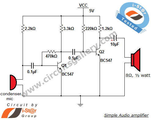
This circuit diagram is a simple and effective design for amplifying weak signals from a capacitive condenser microphone. It is suitable for sound sensing applications and various automatic robotic sensors. While a more complex audio amplifier circuit using the...
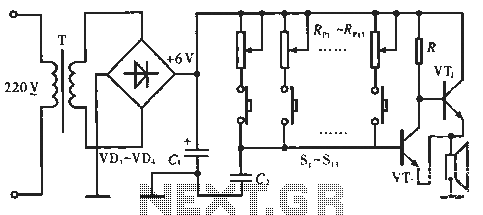
The circuit includes resistors Rp1 to Rp13, which serve dual purposes: they scale the resistance for the keyboard and function as timing resistors for the oscillator. Capacitor C2 acts as a wide discharge capacitor, while switches S1 to S13...
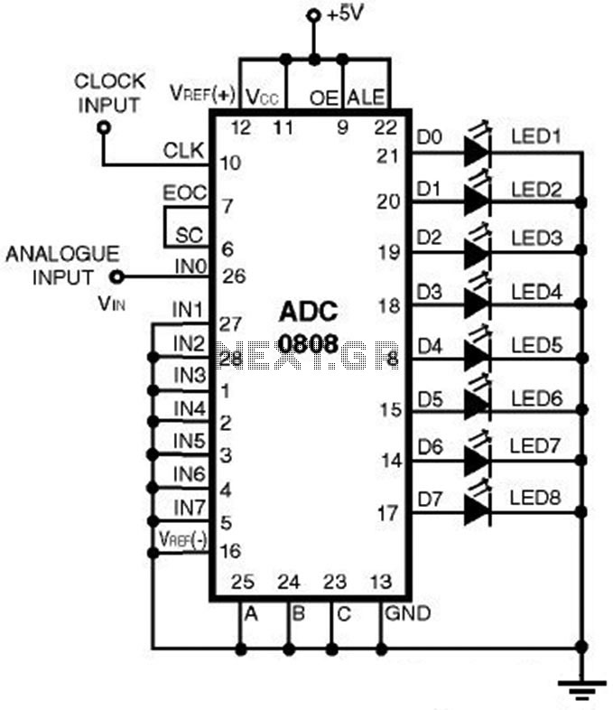
This is a straightforward analog-to-digital converter circuit utilizing an 8-bit analog-to-digital converter (ADC0808). Typically, an analog-to-digital converter (A/D Converter / ADC) necessitates interfacing with a microprocessor to convert analog signals. The ADC0808 is a widely used 8-bit A/D converter that...
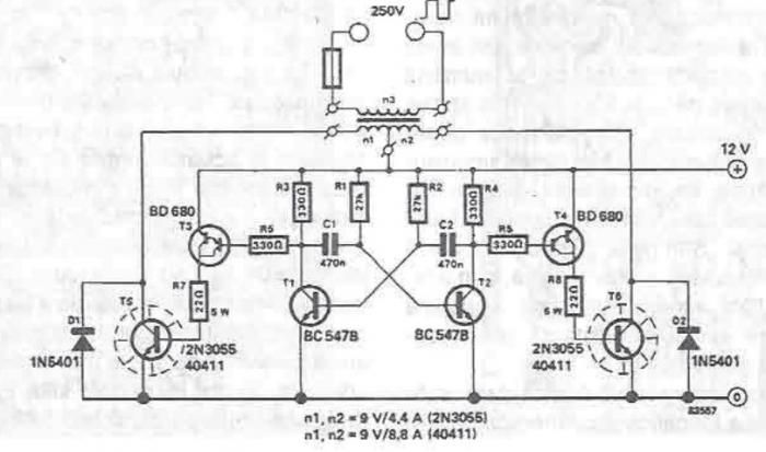
A simple portable converter that transforms 12V to 250V can be constructed using this circuit diagram. This converter is intended for portable use with a 12V car battery. A built astable multivibrator, consisting of transistors T1 and T2, generates...
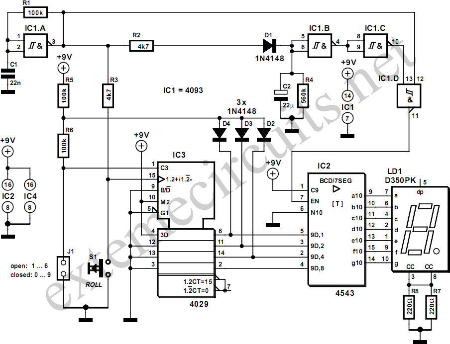
The simplicity of a traditional die makes it exceptionally difficult to create a fully equivalent electronic version, primarily because an electronic version necessitates a power supply and a collection of electronic components that occupy a significantly larger volume than...
This simple electronic buzzer circuit is based on a timer that operates to generate sound frequencies. The NE555 integrated circuit is utilized as an astable multivibrator, functioning at approximately 1 kHz to produce sound when powered on. The frequency...