
SIMPLE EVENT COUNTER
The circuit described consists of several key components designed to function together in a basic counting application. S1 acts as the main power switch, controlling the overall power supply to the circuit. When S1 is in the ON position, the circuit is powered and ready for operation.
The component U2 is responsible for generating a pulse signal. This pulse is triggered when switch S2 is pressed. The pulse generated by U2 serves as an input signal to counter U3, which is a one-digit counter integrated circuit (IC). The primary function of U3 is to count the number of pulses it receives from U2. Each pulse corresponds to an increment in the count displayed by the circuit.
U4 and DISP1 are crucial components for monitoring the output of counter U3. U4 is likely an interface that interprets the digital count from U3, while DISP1 serves as the display unit that visually presents the count to the user. This setup allows for easy observation of the count value in real-time.
Additionally, S3 functions as a reset switch that allows the user to reset the count displayed on DISP1 back to zero. This feature is essential for applications where the count needs to be restarted or cleared for a new counting session.
Overall, this circuit serves as a simple yet effective one-digit counting mechanism, suitable for various applications where a basic count is required. Its design emphasizes ease of use with a straightforward reset function and a clear display of the current count.S1 is a power switch. U2 drives counter U3 by producing a pulse when S2 is depressed. U4 and DISP1 read the count of counter IC U3. S3 is a reset to zero switch. The counter is a basic one-digit circuit useful as a holding block or by itself. 🔗 External reference
Related Circuits
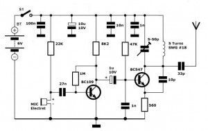
Simple FM Transmitter Circuit This simple FM transmitter circuit was built using a transistor with a transmission distance of about 300m around your home. The simple FM transmitter circuit utilizes a transistor to modulate audio signals onto a radio frequency...
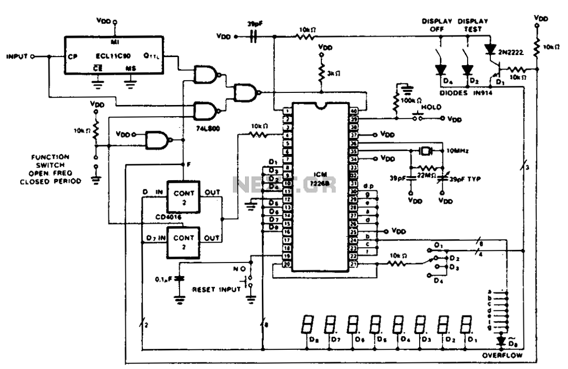
The figure illustrates the application of a CD4016 analog multiplexer to route digital outputs back to the FUNCTION input. The CD4016 functions as a digitally controlled analog transmission gate, eliminating the need for level shifting of the digital output....
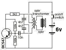
The Colpitts Oscillator is characterized by tapping the mid-point of the capacitive side of the oscillator section. The inductor can be the primary side of a speaker transformer. The feedback comes via the inductor. The Colpitts Oscillator is a type...
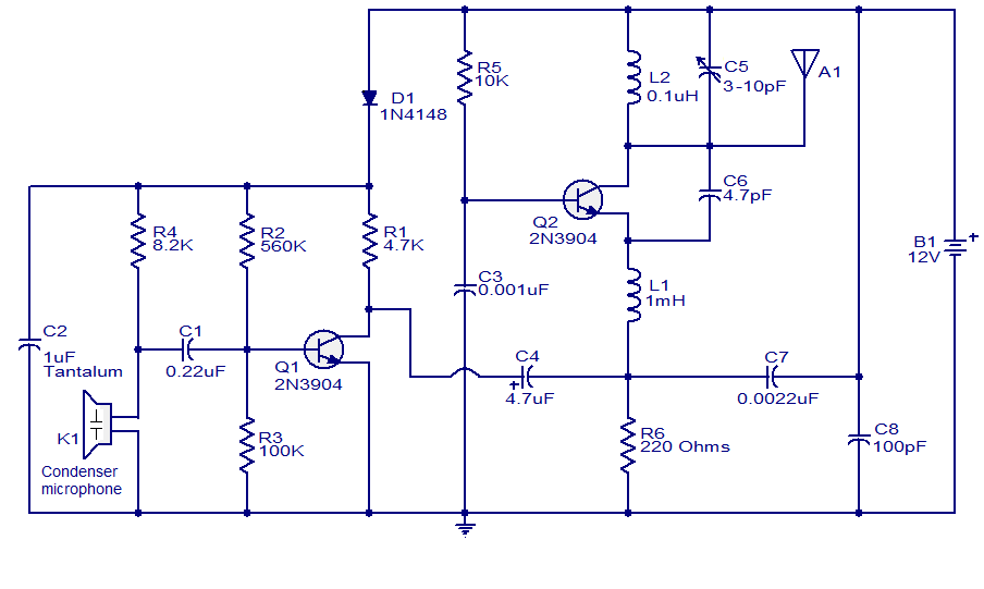
The FM transmitter circuit presented is both stable and simple. With an adaptive antenna, it can achieve a transmission range of approximately 200 meters. This transmitter was developed this year and has yielded positive results. The circuit operates using...
Following the functionality of the standard regenerative front-end receiver circuit, initial output from the transmitter can be observed. The first point of interest in the schematic is located immediately after the LC tuning circuit and the DC blocking capacitor....
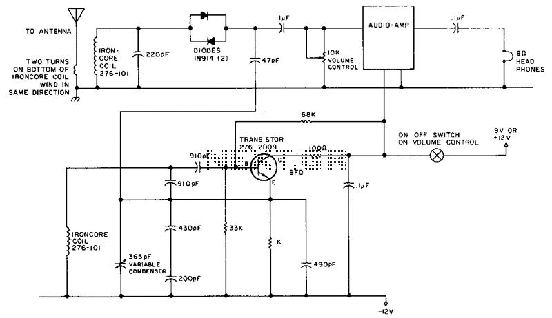
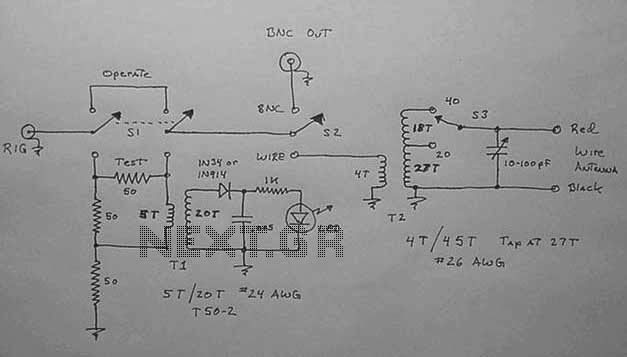
This circuit is designed for operation in the 80m band. It utilizes a 365-pF variable capacitor, specifically intended for the broadcast band, which should be equipped with a vernier drive featuring a six-to-one tuning ratio. This configuration enhances the...
Warning: include(partials/cookie-banner.php): Failed to open stream: Permission denied in /var/www/html/nextgr/view-circuit.php on line 713
Warning: include(): Failed opening 'partials/cookie-banner.php' for inclusion (include_path='.:/usr/share/php') in /var/www/html/nextgr/view-circuit.php on line 713