
Field Strength Meter

The Field Strength Meter circuit is designed to measure the strength of radio frequency (RF) signals in a given area. This type of circuit is particularly valuable for radio frequency hobbyists and enthusiasts who require a practical tool for evaluating signal strength during the development and testing of RF devices.
The circuit typically consists of a few essential components, including a diode, an operational amplifier (op-amp), a microcontroller, and a display unit. The diode is used to rectify the RF signal, converting it into a direct current (DC) voltage that can be processed. The op-amp amplifies this rectified signal, allowing for better sensitivity and accuracy in measurements.
A microcontroller may be implemented to digitize the amplified signal, facilitating the integration of additional features such as calibration, data logging, or signal processing. The output from the microcontroller can be displayed on an LCD or LED screen, providing a visual representation of the field strength.
Power supply requirements for the circuit can vary, but it is common to use a battery or a regulated power supply to ensure stable operation. Additionally, the circuit design may include input impedance matching components to optimize performance across a range of frequencies.
Overall, the Field Strength Meter circuit is a practical tool for anyone working with radio frequencies, enabling effective measurement and analysis of signal strengths in various applications.The following circuit shows about Field Strength Meter Circuit Diagram. Features: useful for radio frequency hobbyist and enthusiast, uses only .. 🔗 External reference
Related Circuits
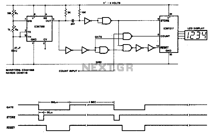
This circuit utilizes the low-power ICM7555 (CMOS 555) to generate the gating, STORE, and RESET signals. The timer is configured as an astable multivibrator to provide the gating signal. Calibration of the system is achieved using a 5 MΩ...
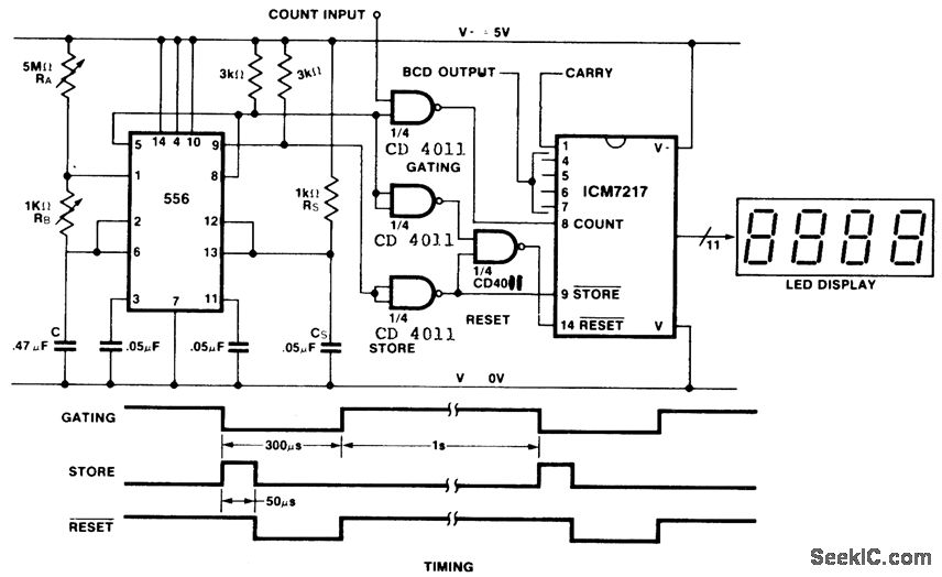
This is an inexpensive frequency counter and tachometer circuit. It utilizes a 556 dual timer to generate the gating, not-store, and not-reset signals for an ICM7217 counter. One timer operates as an astable multivibrator using resistors RA, RB, and...

When the system is placed in a shop or mall, logos and product advertisements serve as an ideal complement to temperature information. For home use, photographs of children at the beach or, should the temperature drop, images of making...
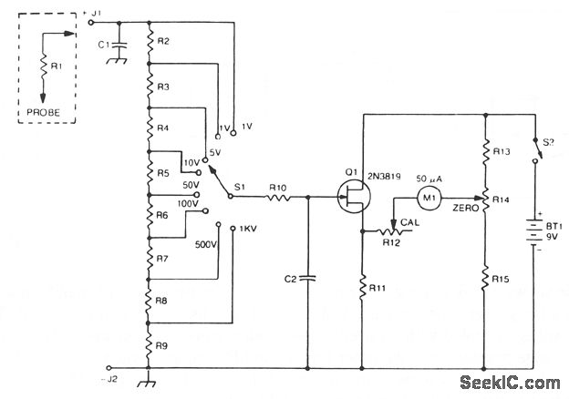
The 2N3819 FET serves as a solid-state voltage output meter (VOM). In this configuration, the 2N3819 functions as a cathode follower. The bias offset, or meter null, is achieved using resistors R14 and R12, while the full-scale calibration is...
Below is a comparator circuit that can measure the voltage of a car battery in steps of 1 volt. The voltage indication is achieved through comparison. The comparator circuit designed for measuring the voltage of a car battery utilizes an...
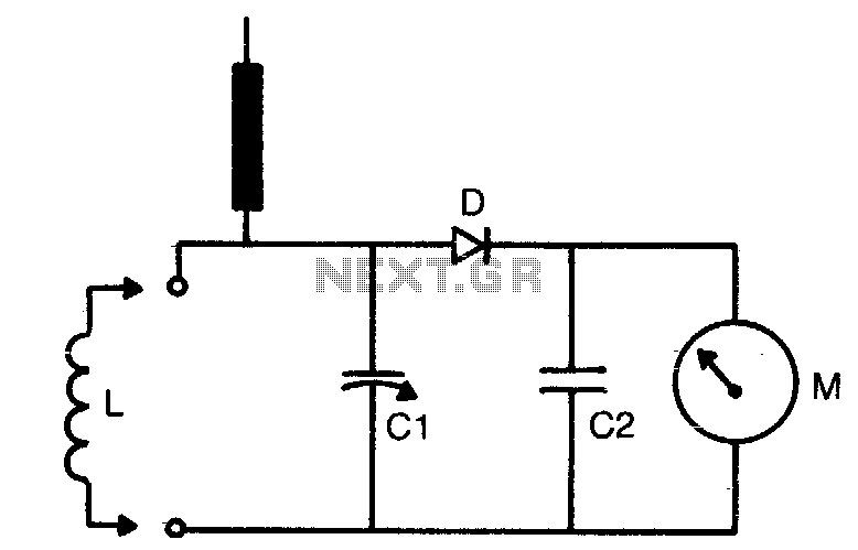
The tuning range is determined by the dimensions of the coil (L) and the setting of the capacitor (C1). Coils can be either plugged in for multi-range use or soldered in place if only a limited frequency range is...