
Simple Function Generator

The described circuit addresses the inherent limitation of conventional triangle-wave generators by incorporating adjustable components that allow for waveform modification. This flexibility is achieved through the use of operational amplifiers, resistors, and capacitors configured in a feedback loop that alters the rise and fall times of the triangle wave.
The circuit can be designed using a standard operational amplifier (op-amp) in an integrator configuration, where the output voltage is proportional to the integral of the input signal. By adjusting the resistor and capacitor values, the frequency and amplitude of the triangle wave can be modified. The addition of a variable resistor (potentiometer) in the feedback loop enables fine-tuning of the waveform characteristics, allowing for a wider range of output signals.
Furthermore, incorporating a comparator circuit can enhance the functionality by providing a square wave output synchronized with the triangle wave. This dual output can be beneficial in various applications, such as waveform generation for signal processing or modulation tasks.
In summary, the modified triangle-wave generator circuit presents a versatile solution for generating customizable waveforms, expanding its utility beyond the limitations of traditional designs.Simple triangle-wave generators have a weakness in that the waveform of their output signal normally cannot be modified. The circuit presented here makes.. 🔗 External reference
Related Circuits

Relays can be utilized to protect motorcycles and have various other applications. When using relays with 6-volt coils, they provide security for "Classic Bikes." The alarms are compact, with completed boards occupying approximately half a cubic inch (8 cc)....

Seven narrow pulses ranging from 2 Hz to 50 kHz are generated by this circuit. Capacitors C1 through C4 provide frequency ranges in decode steps. Resistors R1 and R2 regulate the charging time of capacitors C1 through C4. R2...

This simple circuit is designed to detect RF radiation leakage from transmitters, faulty connections, broken cables, or equipment with inadequate RF shielding. It is specifically tailored for the 2-meter amateur radio band (144-146 MHz in Europe). The device features...
The circuit under discussion is a four-siren sound generator utilizing the UM3561 integrated circuit (IC), which is a low-power CMOS device. Four distinct sounds can be generated by activating switches S1, S2, and S3. This circuit is versatile and...
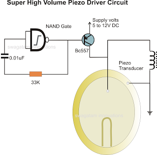
In the previous post, a piezo transducer element was discussed, along with its application in electronic circuits. This article will explore how a piezo transducer can be driven or operated using a simple circuit. The amplification method differs from...
The two circuits di atas illustrate opening a relay contact a short time after the ignition or light switch is turned off. The capacitor is charged and the relay is closed when the voltage at the diode anode rises...