
Basic circuit diagram connection ISO122 124 power supply and signal

The ISO122/124 is a precision isolation amplifier commonly used in applications requiring signal isolation. The circuit design emphasizes the importance of bypass capacitors, which are critical for maintaining stable operation by filtering out high-frequency noise from the power supply. The use of a 1 µF tantalum capacitor is recommended due to its low equivalent series resistance (ESR) and high frequency performance, which ensures effective filtering.
In the schematic, the ISO122/124 should be connected with its power supply terminals receiving the bypass capacitors directly adjacent to the pins. This minimizes the loop area and inductance, which can introduce noise into the system. The placement of the capacitors should be such that the leads are as short as possible, further enhancing the bypassing effect.
Furthermore, the layout of the printed circuit board (PCB) should consider the placement of the ISO122/124 chip and its associated components. Ground planes should be utilized to provide a low-impedance return path, which is essential for maintaining signal integrity. Careful routing of signal traces is also necessary to avoid crosstalk and interference, especially in high-speed applications.
In summary, the proper implementation of the ISO122/124 circuit involves strategic placement of bypass capacitors, careful PCB layout design, and attention to grounding and signal routing. This approach ensures optimal performance of the isolation amplifier in a variety of electronic applications. As shown for the basic connection circuit ISO122/124 power and signals. ISO122/124 each supply terminal must have a 1 F tantalum capacitor as a bypass filter, printed circuit b oard layout and bypass capacitors as close to the chip placement.
Related Circuits
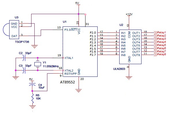
The infrared (IR) circuit is designed to control multiple devices using a TV remote. Unlike standard circuits that can typically switch only one device, this circuit allows for the operation of different devices with the same remote by utilizing...
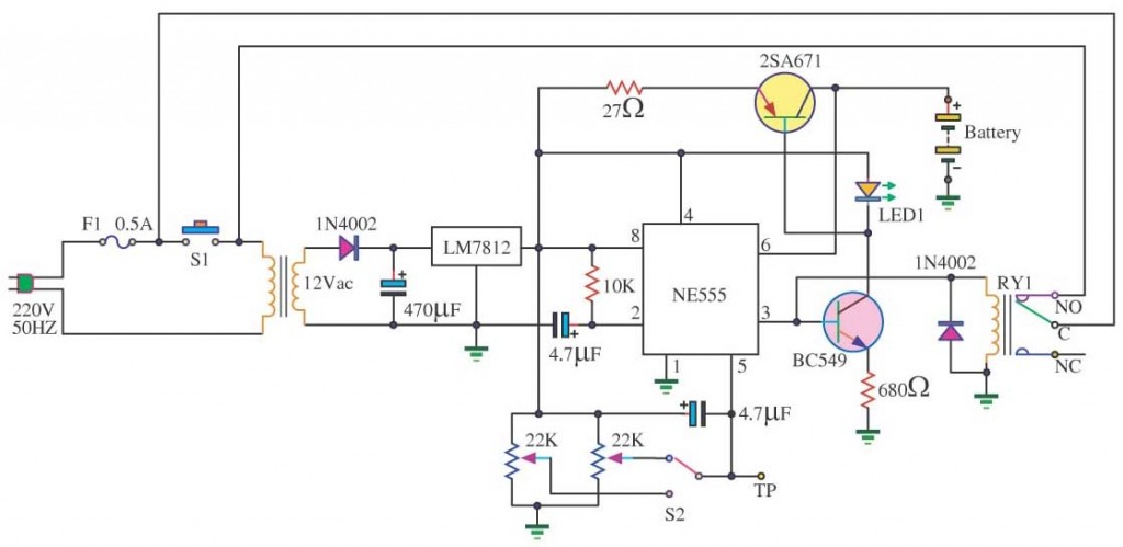
In a lithium-ion cell, a voltage of 3.8V per cell indicates a state of charge of approximately 50%. It is important to note that using voltage as a fuel gauge is not precise, as cells manufactured by different companies...
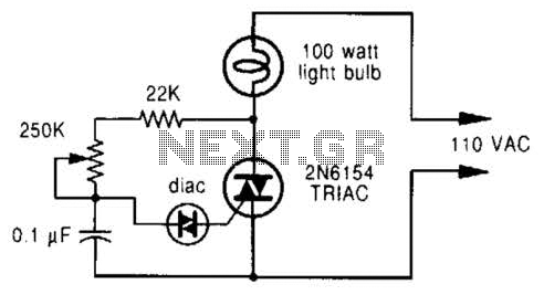
A phase-controlled dimmer delays the triac turn-on to a selected point in each successive AC half cycle. This circuit is suitable only for incandescent lamps, heaters, soldering irons, or universal motors that have brushes. A phase-controlled dimmer is an electronic...

This project is suitable for individuals who enjoy experimenting with electronics. It presents a low risk of damaging the unit. This project involves creating a simple electronic circuit that allows users to engage in hands-on experimentation without significant risk. The...
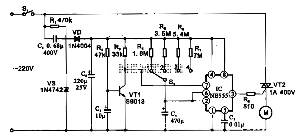
The fan motor driving circuit is depicted as a basic configuration comprising a power circuit and a motor drive circuit. The power supply circuit primarily consists of a power switch (SI), a capacitor (C1), resistors (R1), a Zener diode...
This circuit is a motion detection sensor that utilizes a light source and detector as an infrared motion detector. It incorporates components such as a light-emitting diode (LED), a phototransistor, a transmitter, a receiver, an NE555 timer configured as...