
Simple High Quality Preamp For Hi-Fi
Many of these are not as good as the ones used in this design, and to dismiss a design simply because it uses an op-amp or three is to finish up spending far more than is necessary to obtain the same sonic quality. This is not to say that a good valve preamp (for example) will not sound better (or perhaps just different), but the op-amp sound is a myth which should not be perpetuated (and this is from someone who uses a valve and op-amp preamp, both of my own design).
For those who are still with me, the preamp featured has optional tone and balance controls which may be omitted if desired (although I do not recommend this generally). The input switching may be extended if needed to accommodate more signal sources, however in this version, no RIAA (phono) input is provided see the separate Project Page article for a stand-alone phono preamp which can be added if desired.
The tone controls do not use the traditional Baxandall feedback design, but are basic passive controls, which offer a modest 6dB of boost and cut at maximum. This may not sound like much (most tone controls offer 12 to 20dB), but in reality is usually quite sufficient for such minor corrections as are usually needed.
(Note that these tone controls can also be used in the Project 88 preamp). NOTE: The tone controls have been changed slightly from the original publication of this circuit. The treble control should ideally use a 1nF capacitor (10nF was used previously). As now shown, there will be 3dB of boost or cut at 6kHz and 55Hz with the controls at maximum. (I did say that they were subtle!) If the effect is too subtle, increasing the value of the bass and treble caps (100nF and 1nF respectively) will lower the frequency, and vice versa. Some people may find that the bass control is better with a 47nF capacitor this will almost certainly be the case with small loudspeaker systems.
A tape output is provided this can be left out if not needed, but again I would suggest that it is worthwhile keeping. The following shows the inputs and switching circuitry. Construction is not overly critical, but care should be taken to ensure that left and right channel wiring is kept separated wherever possible to prevent crosstalk.
All input switching should be performed using an extended shaft rotary switch. This allows all inputs to be shielded in their own section, and reduces the amount of shielded cable required. The input level controls for CD and Tuner inputs allows the levels to be balanced, so that with a little experimenation, it should be possible to switch from one input to any other and retain the same volume.
Note that the traditional tape monitor switch has not been included, since I suspect it is rarely used these days. If needed, it can easily be accommodated. The Tape Out connectors are wired back to the input amp, so would have had a gain of 2 (6dB) without the attenuator.
This also provides useful buffering of the input amp from any nasties which could occur (shorted signal leads, etc), and prevents variations in signal when the tape is connected. Only the left channel is shown in full, the right channel is identical, and uses the B halves of the NE5532 op-amps (pinouts are shown for reference).
Note that power is connected to the op-amps The input stage has a gain of two (6dB), and is also the buffer for the tone controls. The tone control buffer also has a gain of two to make up for losses in the tone control stage (6dB), so the total gain after the tone controls is four (for those frequencies which are boosted to the maximum).
Allowing for 2V RMS from a CD player, this is 8V RMS, or a peak swing of 11. 3V in either direction (assuming the input level control is fully advanced and maximum boost is applied). This requires a power supply voltage of +/- 15V to ensure that the signal will not clip. Other levels will be considerably below the 2V RMS of the CD player, and are completely safe from clipping.
Note that the tone controls are almost completely flat when centred any deviation from flat response is more likely to be mechanical rather than electrical. When switched out, the controls and the buffer amp are removed from the circuit. The final section provides the bulk of the gain (12. 6dB), and includes the volume and balance controls. The balance control introduces a loss of 2. 3dB in the centre position, and has a semi-log characteristic, so fine control about the centre position is very easy and precise.
When the control is rotated to one extreme or the other, the opposite channel gains 1dB of signal. Using a gain controlled stage here would lower noise, but this is not expected to be a problem. If your amplifier is of unusually high sensitivity, simply increase the value of R19 gain of this stage is given by Total system gain with all controls (other than tone) at maximum is 18. 5dB, so 230mV will drive an amp with a 2V input sensitivity to full power. If more gain is required (which is rather unlikely), this may be obtained by reducing the value of R19 in the final output stage (currently 22k).
If for example you needed a total gain of 24dB, the value of R19 must be reduced to 12k. Expect noise to increase in proportion as gain is raised. I have found that with power amps of typical sensitivity (about 27dB gain), an overall preamp gain of 10dB is sufficient with most sources. This may be achieved by increasing R19 to 82k, so the overall gain will be If you wanted to, the values of R19 and R20 can be divided by 10 (to 10k and 2.
2k as shown). This may reduce noise by a marginal amount because of the lower impedances. I have not measured the noise levels in both configurations, but they will be very low either way. Each op-amp should be bypassed with a 10uF/25V electrolytic from each supply lead to ground, and a 100nF capacitor between supply leads (not shown in diagrams). The latter should be as close as practicable to the op-amp supply pins, and the 10uF caps can be almost anywhere you like.
The op-amps specified are premium devices, but should be reaspage. 🔗 External reference
Related Circuits
This is a simple function generator built around a single 8038 waveform generator IC. The circuit is capable of producing sine, square, or triangle waves within a frequency range of 20Hz to 200kHz. The function generator circuit utilizes the 8038...
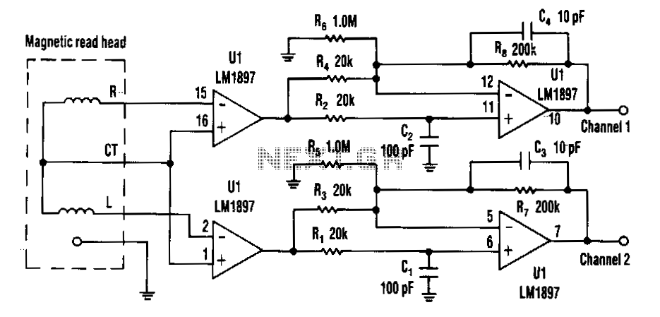
Choosing direct current (DC) coupling instead of alternating current (AC) coupling can significantly reduce the noise associated with preamplifiers for a magnetic reading head, particularly at low frequencies. The LM1897 eliminates the need for the capacitor that typically AC...
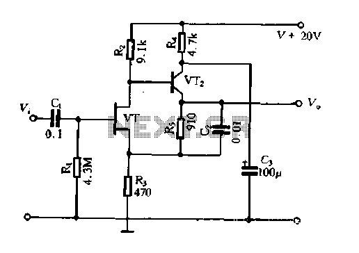
The Field Effect Transistor (FET) exhibits a high input impedance, allowing the construction of high input impedance amplifiers. However, as a FET amplifying device, the distributed capacitance and the Miller effect significantly increase input capacitance at high frequencies. Furthermore,...

The hardware design for USB is quite minimal, which is advantageous. However, it quickly becomes apparent that the simplicity of the hardware design leads to complex communication and control software, which will be explored further in the theory and...
The receiver is a triple superheterodyne receiver with two phase-locked loop (PLL) guided local oscillators. The first local oscillator (LO) operates at 2.1 GHz and can be adjusted in increments of 500 kHz, down-converting the received signal to a...
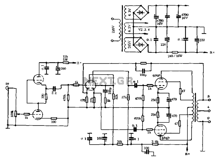
The self-generated bias amplifier tube is designed for each tube individually to alleviate the challenges faced by amateur conditions in paired amplifiers. It includes a separate DC filament power supply, which minimizes the risk of induced cross-linking and enhances...
Warning: include(partials/cookie-banner.php): Failed to open stream: Permission denied in /var/www/html/nextgr/view-circuit.php on line 713
Warning: include(): Failed opening 'partials/cookie-banner.php' for inclusion (include_path='.:/usr/share/php') in /var/www/html/nextgr/view-circuit.php on line 713