
Simple PIC USB Interface Circuit

The USB hardware design primarily revolves around the integration of the PIC 18F4455 microcontroller, which is responsible for processing inputs and managing communications with the laptop. The LM7805 voltage regulator ensures that the microcontroller receives a stable 5V supply, crucial for reliable operation. The 47µF capacitors are essential in filtering out any voltage spikes or noise, ensuring that the microcontroller operates smoothly without erratic behavior caused by power fluctuations.
The USB connector must be wired correctly, as the D+ and D- signals are critical for proper USB communication. A mistake in wiring can lead to the device not being recognized by the host, thus troubleshooting these connections is a fundamental step in the design process. The toggle LEDs provide visual feedback for the user, indicating the state of the outputs controlled by the microcontroller.
The A/D conversion process is vital for capturing analog signals and converting them into a digital format that can be processed by the microcontroller. The signal from the trimpot is fed into the RA0 pin, where it is converted and subsequently sent to the laptop. This data transmission is facilitated by the USB protocol, which allows for efficient and reliable communication between the microcontroller and the host computer.
In addition to the trimpot value, the push button adds interactivity to the design. The ability to notify the laptop application when the button is pressed enhances the user experience and demonstrates the capabilities of the USB interface for input handling. Overall, while the hardware design is straightforward, the integration of software and communication protocols introduces layers of complexity that are essential for achieving a functional USB device.Hardware design for USB is actually quite minimal, which is a big plus for us. However, what you quickly find out with USB is that the easy hardware design means the communication and control software is very complex, we`ll see more about that in the theory and software sections. The main devices used in the circuit are the PIC 18F4455, USB Connector and LM7805. The +5v output from the power circuit comes from the LM7805 regulator. Notice the 47uF capacitors on the input and output. These are meant to be DC filtering capacitors, which smooth out the constant DC voltage being fed to the microcontroller from the 7805 regulator. Make sure you double check your USB pinout. A common mistake when wiring the PIC to the USB connector is getting the D+ and D- signals backwards.
So if you`re sure that the PIC is running your perfect code, but the USB device isn`t coming up properly, switch D+ and D-, it might just magically fix your problem! The output LEDs will be simple `toggle` LEDs. The program running on our laptop will be able to toggle them on and off with the push of a button. The A/D circuit is a standard 3 pin, Connected to Power, Signal Out and Ground circuit. The signal output goes into RA0 which is the Analog to Digital converter. After the PIC converts this signal it should send the data to the Laptop via USB. The laptop will the visually display the trimpot`s value. The push button will do a similar thing, when the button is pushed, the laptop application should update with a notification that it has been pressed.
These are simple ideas, but when done over USB they become rather complicated as we`ll see in the theory section. 🔗 External reference
Related Circuits
This circuit represents a Dive computer interface for RS232. Uses the MAX232A. The described circuit serves as an interface for a dive computer utilizing the RS232 communication protocol, incorporating the MAX232A integrated circuit. The MAX232A is a dual voltage-level converter...
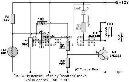
The following page outlines detail information on how to step by step design a Simple Heat Sensor Circuit. This circuit design utilized LM741 as the operational amplifier. More: Circuit Parts/Components List: Re1 = 12V relay R1 = 47K R2...
The following circuit illustrates a timer circuit with independent mark and space periods. It is based on the 7555 integrated circuit (IC). The high output duration is calculated by T(on) = 0.7 Ra Ct, while the low output duration...
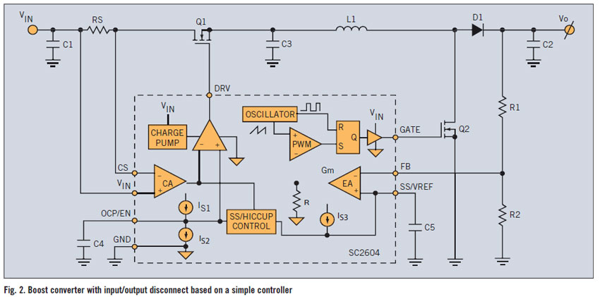
A PWM boost converter in a simple controller has a DC path from input VIN to VOUT, which is utilized for high-efficiency power conversion. A PWM (Pulse Width Modulation) boost converter is an essential component in power electronics, designed to...
This audio processor circuit utilizes the SSM2045 integrated circuit (IC), specifically designed for electronic music applications, alongside the 741 operational amplifier (op-amp) IC. The audio processor circuit is centered around the SSM2045, which is renowned for its ability to provide...
The circuit receives its input from the zero-crossing detector, which generates a 0-to-1-to-0 pulse to set the R-S flip-flop and activate the ramp circuit (A to Ramp) to initiate the timing ramp ascent. The described circuit operates by utilizing a...
Warning: include(partials/cookie-banner.php): Failed to open stream: Permission denied in /var/www/html/nextgr/view-circuit.php on line 713
Warning: include(): Failed opening 'partials/cookie-banner.php' for inclusion (include_path='.:/usr/share/php') in /var/www/html/nextgr/view-circuit.php on line 713