
YENKA simple series circuit voltage diagram. voltages calculated problem

In a basic series circuit, components are connected end-to-end, forming a single path for current flow. The total voltage supplied by the power source is distributed across the components. According to Ohm's Law, the voltage drop across each component can be determined by the formula V = I * R, where V represents the voltage drop, I is the current flowing through the circuit, and R is the resistance of the component.
In a series circuit, the current remains constant throughout all components, while the total resistance is the sum of the individual resistances. The total voltage across the circuit is equal to the sum of the individual voltage drops across each component. For example, if a series circuit consists of a 12V power supply and two resistors of 4Ω and 8Ω, the total resistance would be 12Ω. The current flowing through the circuit can be calculated using Ohm's Law: I = V / R = 12V / 12Ω = 1A.
The voltage drop across each resistor can then be calculated: for the 4Ω resistor, V1 = I * R1 = 1A * 4Ω = 4V, and for the 8Ω resistor, V2 = I * R2 = 1A * 8Ω = 8V. The sum of the voltage drops (4V + 8V) equals the total voltage supplied (12V), confirming the principle of conservation of energy in the circuit.
YENKA software can facilitate the visualization of these calculations and the overall circuit behavior, providing a dynamic environment for exploring circuit theory and practical applications. Understanding these principles is crucial for accurate circuit design and analysis.hi, i am using YENKA to diagram circuits. i dont get what it is doing when working out voltages in a basic series circuit. the picattached showsthe.. 🔗 External reference
Related Circuits
The SC41343 is designed as a type of infrared, ultrasonic, or RF remote control launch coding circuit. The internal circuit comprises a sequence generator, control logic circuit, 4-bit shift register, data extraction circuit, and latch circuit. Features include the...
The pulser is designed to switch the mains voltage on and off at intervals ranging from just under one second to up to 10 minutes. This functionality is particularly useful for testing mains-operated equipment over extended periods or for...
This is a low-cost 150-watt amplifier circuit with a diagram and schematic design utilizing two Darlington power transistors, TIP142 and TIP147. The 150-watt amplifier circuit is designed to provide high power output while maintaining cost efficiency, making it suitable for...
This project was designed and constructed as enhancement to the 0-30V Stabilized Power Supply Project with the DIY electronics hobbyist in mind. The circuit uses a single PIC Microchip to perform the Voltage, Current and Temperature conversions and display...
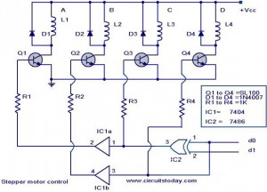
The following circuit illustrates a Stepper Motor Controller Circuit Diagram. This circuit is based on the 7404 IC. Features include a simple stepper motor. The stepper motor controller circuit utilizing the 7404 IC is designed to drive a stepper motor...
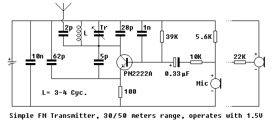
A simple FM transmitter utilizing a single transistor. Mini FM transmitters are commonly regarded as one of the fundamental circuit types for beginners in amateur electronics. When constructed correctly, they offer clear wireless sound transmission via a standard FM...