
Simple Infrared Control Extender

More: The photodiode D4 is connected to the inverting input of a 741 operational amplifier (op-amp) through a resistor (R2) and a capacitor (C1). The BPW41 photodiode, sourced from Vishay/Telefunken, requires reverse biasing to convert light energy into an equivalent voltage; hence, it is also connected to the positive supply rail via resistor R1. The non-inverting input of the op-amp is maintained at half the supply voltage using two equal resistors, R3 and R4. Following the op-amp, a BD240 transistor is utilized as an after-burner, which can supply substantial current pulses to infrared LEDs D2 and D3. It is important to note that the pulsed current through the LD274 infrared emitters should not exceed approximately 100 mA, necessitating the inclusion of a fixed resistor in series with a preset resistor (P1). An additional visible-light LED (D1) is incorporated to flash when an infrared signal is detected from the remote control. Care should be taken when adjusting the setting of P1 to ensure that the current through the infrared emitters does not exceed the minimum required to effectively reach the intended destination of the infrared signal. The currents referenced are peak levels due to the low duty cycle of the infrared pulses; thus, the average current drawn from the battery will be significantly lower. The directivity of the infrared LEDs, and consequently the range of the control extender, can be enhanced by equipping the LEDs with reflective caps.
This circuit effectively extends the range of infrared remote controls by utilizing a photodiode for signal reception and an operational amplifier for signal amplification. The design includes provisions for current limiting and signal indication, ensuring reliable operation while maintaining efficiency. The use of reflective caps on the infrared LEDs can further optimize performance, allowing for greater control distances and improved signal directionality. The careful selection and configuration of components, including resistors and capacitors, contribute to the overall functionality and reliability of the circuit, making it suitable for various consumer electronic applications.Lots of consumer electronic equipment like TV sets, VCRs, CD and DVD players employs infrared remote control. In some cases, it is desirable to extend the range of the available control and this circuit fits the bill, receiving the IR signal from your remote control and re-transmitting it, for example, around a corner into another room.
Photodiode D4 is connected to the inverting input of a 741 opamp through resistor R2 and capacitor C1. Since the BPW41 photodiode (from Vishay/Telefunken) needs to be reverse-biased to turn light energy into a corresponding voltage, it is also connected to the positive supply rail via R1. The non-inverting input of the 741 is held at half the supply voltage by means of equal resistors R3 and R4.
The opamp is followed by a BD240 after-burner transistor capable of supplying quite high current pulses through IR LEDs D2 and D3. However, the pulsed current through the LD274s should not exceed 100 mA or so, hence a fixed resistor is used in series with preset P1.
D1 is an ordinary visible-light LED that flashes when an IR signal is received from the remote. With regard to the setting of P1, do not make the IRED current higher than necessary to reliably reach the final destination of the IR signal. Also, the currents mentioned above are peak levels due to the small duty factor of the IR pulses, the average current drawn from the battery will be much smaller.
The directivity of the IR LEDs and consequently the range of the control extender may be increased by fitting the devices with reflective caps. 🔗 External reference
Related Circuits

When the supply voltage drops below a minimum threshold, it is often advisable to disconnect the supply from the system to prevent poor performance or erratic operation. The circuit presented achieves this with minimal cost, board space, and complexity....

The Infrared IR Receiver circuit consists of a phototransistor, a microcontroller, and an amplifier. Understanding the data transfer between these three components is essential for successfully operating the circuit. The phototransistor receives digitally encoded data from an IR emitting...
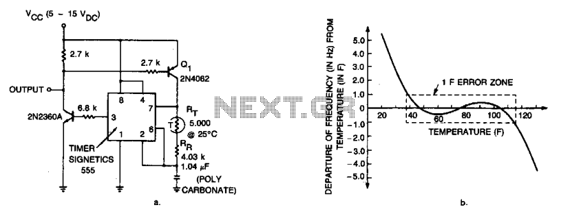
A pair of transistors and a thermistor in the charging network of a 555 timer allow this device to sense temperature and generate a corresponding frequency output. The circuit maintains an accuracy of ±1 Hz over a temperature range...
The water level controller circuit described here controls the water level inside a tank. There are two modes available with this water level controller circuit. The water level controller circuit is designed to maintain the water level within a specified...
The LTC3731H is a linear three-phase step-down voltage regulation power control unit from the company, capable of driving N-channel MOSFETs. It operates within a temperature range of up to 140°C and supports a control frequency of up to 600...
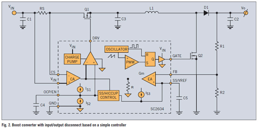
A PWM boost converter in a simple controller has a DC path from input VIN to VOUT, which is utilized for high-efficiency power conversion. A PWM (Pulse Width Modulation) boost converter is an essential component in power electronics, designed to...