
Temperature control

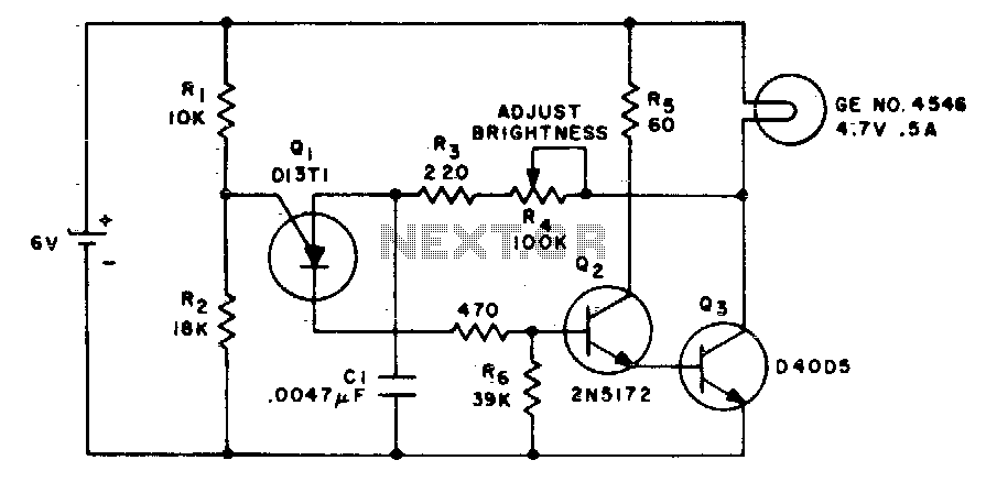
The described circuit utilizes a 555 timer in astable mode, where the frequency of oscillation is influenced by the electrical resistance of a thermistor, which varies with temperature changes. The thermistor is typically a negative temperature coefficient (NTC) type, meaning its resistance decreases as temperature increases. This characteristic allows the circuit to produce a frequency output that corresponds to the ambient temperature.
In the charging network, two transistors are employed to amplify the signal from the thermistor and to provide stability to the frequency output. The configuration of these transistors can help in managing the current flow through the thermistor and enhancing the sensitivity of the temperature measurement. The output frequency is derived from the time constant established by the charging and discharging cycles of the capacitor in conjunction with the variable resistance of the thermistor.
The accuracy of ±1 Hz over a temperature range signifies that the circuit is designed for precise temperature monitoring applications, making it suitable for environments where temperature stability is crucial. The 555 timer's ability to operate with a wide supply voltage range adds to the versatility of the circuit, enabling it to be integrated into various electronic systems for temperature sensing and control.
Overall, this circuit represents an efficient approach to temperature measurement, utilizing common electronic components to achieve reliable performance in real-world applications.A couple of transistors and a thermistor in the charging network of the 555 type timer enable this device to sense temperature ^nd produce a corresponding frequency output. The circuit is accurate to within ±1 Hz over a 78°F temperature range.
Related Circuits
The IC1A operational amplifier is configured as an inverting amplifier, with its gain determined by a three-way switch that connects different resistor values in parallel to R4. Following this input stage is an active three-band tone control circuit, designed...
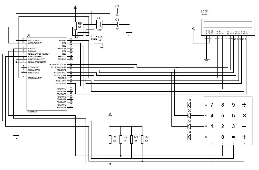
A beginner or hobbyist is seeking to learn more about microcontrollers. The objective is to display an output on an LCD when a button on the keypad is pressed. To achieve the desired functionality of displaying output on an LCD...
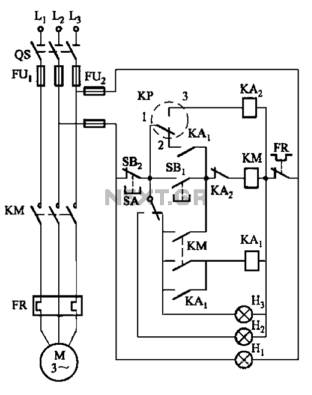
An air compressor is commonly utilized in electrical equipment factories and is typically controlled by electrical contacts. The circuit diagram is depicted in Figure 5-1. The circuit allows for both automatic and manual operation. In the diagram, KP represents...
This circuit alters the average value of the DC supply voltage due to the high switching frequency. The tungsten lamp will exhibit an almost continuous adjustable light output ranging from 0 to 100%. If a light-emitting diode is utilized...
The project utilizes a 10 x 20 grid of RGB LEDs controlled by the myRIO. It is operated through a web interface on any device that supports WebSockets. Originally, the system was built using an Arduino, but the creator...
The basic small-range remote controls are Infrared and RF (Radio Frequency). One of the weaknesses of Infrared is that the signal cannot pass through walls. Therefore, to control a garage door, an RF remote control is necessary. The circuit...