
simple pwm boost converter io disconnect solves malfunctions
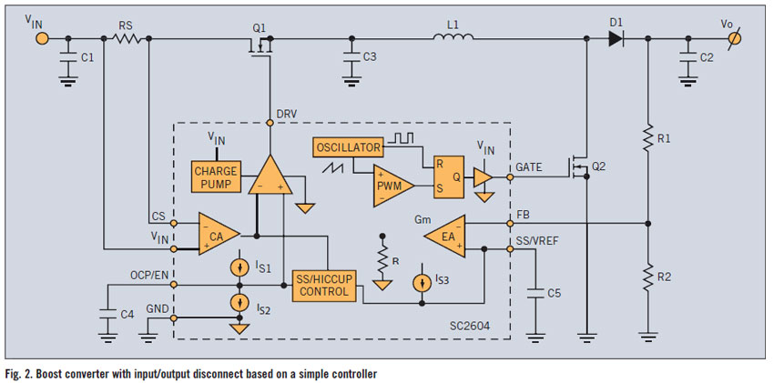
A PWM (Pulse Width Modulation) boost converter is an essential component in power electronics, designed to step up a lower input voltage (VIN) to a higher output voltage (VOUT) while maintaining high efficiency. The operation of this converter relies on the control of the duty cycle of the switching element, typically a transistor, to regulate the output voltage.
The circuit typically consists of several key components: an inductor, a switch (transistor), a diode, and a capacitor. The inductor stores energy when the switch is closed and releases it to the output when the switch is open. The PWM controller adjusts the duty cycle of the switch to control the amount of energy transferred to the output, ensuring that VOUT remains stable despite variations in VIN or load conditions.
The DC path from VIN to VOUT implies that there is a direct electrical connection between the input and output, which is crucial for maintaining efficiency during the conversion process. This connection allows for minimal energy loss, as the converter can directly transfer the input voltage to the output when the switch is in the appropriate state.
In summary, a PWM boost converter is a vital circuit for applications requiring voltage step-up with high efficiency, leveraging a simple controller to manage the power conversion process effectively.A PWM boost converter in a simple controller has a DC path from input VIN to VOUT, which is utilized for high-efficiency power conversion.. 🔗 External reference
Related Circuits
If one has considered experimenting with pulse-width modulation, this circuit serves as an excellent starting point. The design prioritizes simplicity by utilizing a dual 555 timer, making the assembly straightforward. A small PCB has been created for this purpose,...
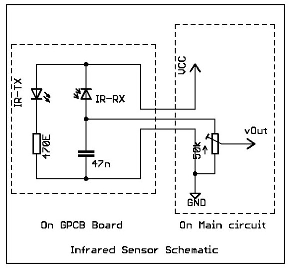
Overview: This tutorial demonstrates the creation of a simple infrared sensor module designed to detect reflecting surfaces. This sensor is capable of identifying reflective materials such as silver or white strips, as well as serving applications in obstacle detection...
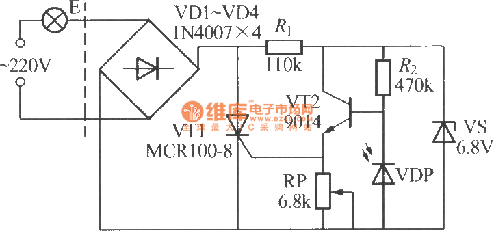
The VDP is a photodiode that exhibits low resistance during the day, approximately 1 kΩ. As a result, transistor VT2 remains off, which keeps thyristor VT1 in the off-state due to the absence of trigger current at the gate,...
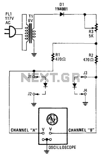
Suitable for matching diodes or examining the VI characteristics of two-terminal devices (such as diodes), this circuit is designed for laboratory use. Resistors R1 and R2 can be increased in value, and a higher voltage transformer can be utilized...
A simple water level sensor or liquid level detector for measuring or detecting a required level of water, liquid, or fluid in a tank, pool, well, aquarium, washing machine, etc. The water level sensor is an essential device utilized for...
The circuit presented generates a smooth, piercing, wailing siren with minimal components. Additionally, three spare gates of the hex inverter IC1 are available, allowing the possibility of creating a cacophony by operating two sirens from the same integrated circuit....