
2500w phase control
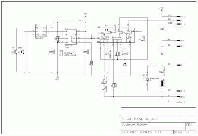
This circuit is designed to manage both resistive and inductive loads with a maximum power rating of 2,500W, making it suitable for a variety of applications in industrial and consumer electronics. The Siemens TLE3103 serves as the core component, integrating essential functionalities such as power supply, zero-crossing detection, and logic control. The zero-voltage crossing detector is crucial for minimizing electromagnetic interference and reducing switching losses, thereby enhancing the efficiency of the circuit when controlling AC loads.
The logic driver within the TLE3103 is controlled by a low voltage input, which allows for the triac firing mechanism to be enabled or disabled based on the state of pin 13. This design provides flexibility in operation, as the trigger output can be actively controlled by the user interface. The inclusion of UP and DOWN buttons allows for fine-tuning of the output power level through the AD5228 digital potentiometer, which provides a smooth adjustment range across 32 discrete steps. The MAX6817 debouncer ensures stable operation of the buttons, preventing false triggering due to mechanical bounce.
The power-on reset feature of the digital potentiometer is particularly beneficial, as it can be configured to start at a predetermined level based on the connection of its reset pin. This adaptability can be utilized to tailor the circuit's behavior to specific application requirements.
For load handling, the BTA41 triac is selected for its robust performance, capable of managing loads up to 40A. This choice, while exceeding the circuit's power requirements, enhances safety due to its isolated body design, which mitigates risks associated with accidental contact during maintenance or operation.
In terms of inductance, the circuit is initially designed with a 68H inductor. However, there is an option to replace this with a 100-ohm resistor, which would necessitate a change in the capacitor C5 to a value of 47nF. This modification allows for flexibility in tuning the circuit's response characteristics, accommodating various load types and operational conditions. The careful selection of components and configuration parameters ensures that the circuit remains efficient, reliable, and safe for controlling high-power applications.This circuit controls resistive and inductive loads up to 2, 500W. It`s main functional device is an integrated phase control circuit - Siemens TLE3103. It contains its own power supply, a zero voltage crossing detector circuit and a logic driver. An additional feature is the low voltage input to enable/disable triac firing enabling/disabling the l ogic driver. The function is as follows: pin13 TLE3103 open (floating), trigger output active, tied to ground trigger output disabled. An UP and a DOWN button control a 32-step digital potentiometer (IC2, AD5228) via the debouncer IC1 (MAX6817).
The potentiometer has a power on reset pin which might be tied to ground causing the potentiometer to start at midscale, or to VCC causing it to start at zero scale. The desired function is selectable using jumper JP1. The triac (capable of driving 40A loads) is a bit overkill for the desired power but the BTA41 has an isolated body and therefore handling of the board under voltage is less dangerous as it is with phase on the package.
The circuit uses a 68 H inductance, but this might be replaced with a 100 resistor, then replacing the inductance C5 should have a value of 47nF. 🔗 External reference
Related Circuits
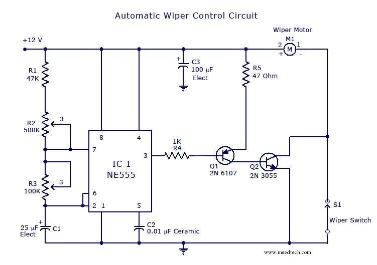
The circuit is built around an astable multivibrator using the NE555 timer. The output at pin 3 remains high for a duration determined by resistor R2 and low for a duration set by resistor R3. The low output pulse...
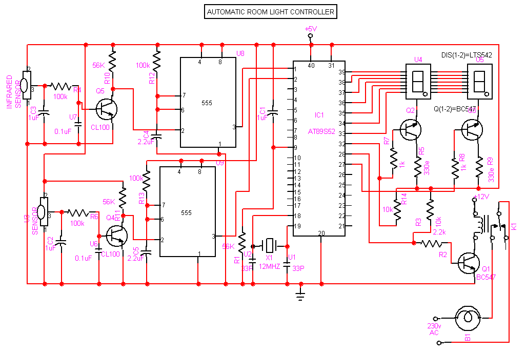
This project involves an automatic room light controller with a visitor counter utilizing a microcontroller. It is a dependable circuit designed to manage room lighting while accurately counting the number of individuals present. When a person enters the room,...
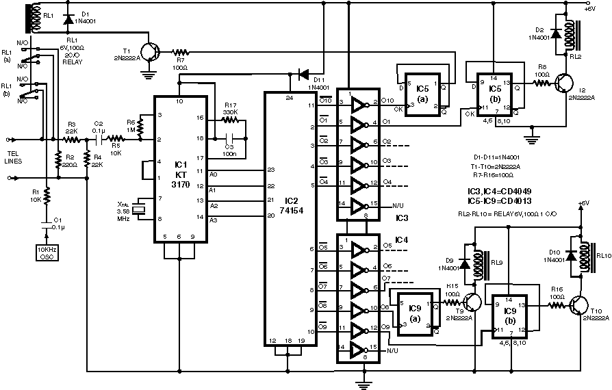
This circuit enables the remote switching of appliances via telephone lines. It allows for the control of appliances from any distance, surpassing the limitations of infrared and radio remote controls. The design accommodates up to nine appliances, corresponding to...
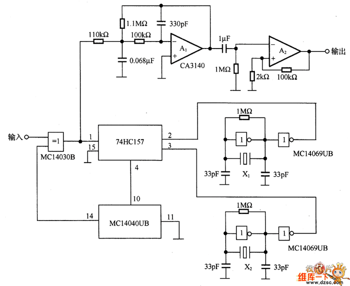
Figure 7-2 illustrates the FSK (Frequency Shift Keying) signal demodulation circuit, which is built using a digital phase-locked loop. This circuit features two oscillators operating at distinct frequencies: crystal oscillator X with a frequency of 983.04 kHz and crystal...
This DC drill speed controller circuit allows for the adjustment of the rotational speed of a drilling machine. A mini-drill machine is always... This circuit utilizes a pulse-width modulation (PWM) technique to control the speed of a DC motor, which...
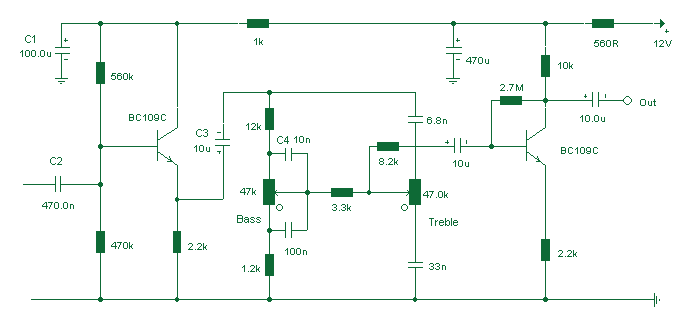
Based on the classic Baxendall tone control circuit, this provides a maximum cut and boost of around 10dB at 10K and 50Hz. The first BC109C transistor (left hand side) is acting as a buffer. It provides the circuit with...
Warning: include(partials/cookie-banner.php): Failed to open stream: Permission denied in /var/www/html/nextgr/view-circuit.php on line 713
Warning: include(): Failed opening 'partials/cookie-banner.php' for inclusion (include_path='.:/usr/share/php') in /var/www/html/nextgr/view-circuit.php on line 713