
Packard Bell Remote Control

The remote control system operates by sending out a specific sequence of pulses that encode information regarding the button pressed. The preamble serves as a synchronization signal, allowing the receiving device to prepare for the incoming data. The encoding scheme employed involves measuring the duration of the pulses to determine the binary values being transmitted. Each pulse duration corresponds to a specific bit, with longer pulses typically representing binary '1' and shorter pulses representing binary '0'.
The data structure consists of four bytes, where the first two bytes are dedicated to identifying the remote control itself, while the last two bytes encode the specific button pressed. The checksum mechanism, where the second byte is the complement of the first, provides a simple yet effective means of error detection. This ensures that if the data is corrupted during transmission, the receiving end can identify discrepancies in the expected values.
For the Help button, the encoded data is structured as follows: the first byte (08) identifies the remote control, the second byte (F7) serves as a checksum, the third byte (20) indicates the Help button, and the final byte (DF) is the checksum for the button ID. This systematic approach to encoding and error-checking enhances the reliability of the remote control system.
The decoding process involves the analysis of incoming pulse lengths to confirm the presence of the preamble and validate the data. The hc11 and 8051 microcontrollers interpret the data differently, highlighting the flexibility of the design to accommodate various hardware implementations. Overall, this remote control system exemplifies a robust method of data transmission, ensuring accurate communication between the remote and the controlled device.When a key is pressed the remote control sends a preamble followed by 32 bits of information encoded using these pulse timings. Examples of these pulses can be seen below as logic analyser screen dumps (the glitches are bugs in the Logic analyser software).
The 32 bits of information are made up of four bytes, 2 bytes of remote control ID and 2 bytes of button ID received MSB first in this order. The second of each pair of bytes is always the complement of the first (as a basic form of checksum). The remote control ID is always 08, thus the first two bytes are always 08 F7 hex. Thus the 32 bit data for the Help button (Button ID of 20 hex) would look like 08 F7 20 DF encoded as above.
Codes for all keys are shown in the image below (click on it for a larger version) The code shown above decodes these codes. It measures the incoming pulses looking first for a preamble of the right length and then looking for valid data encoding to extract the code for the pressed button.
The hc11 version works off the inverted code (second byte), the 8051 works off the first. 🔗 External reference
Related Circuits

A simple frequency meter or frequency counter circuit featuring an LCD display and an AVR microcontroller. This includes a DIY schematic circuit diagram and embedded C code. The frequency meter circuit is designed to measure the frequency of input signals...
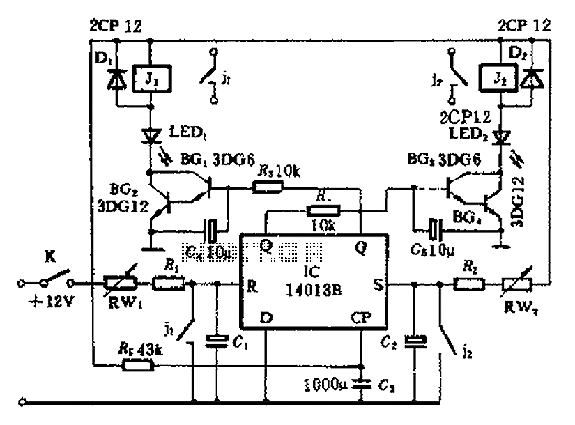
The timing control circuit is a sequential circuit that allows for sequential timed control of two switches. The control time can be adjusted from a few seconds to several tens of seconds. If mechanical control is applied for reciprocating...
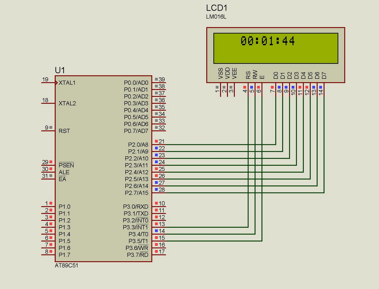
This project implements a real-time clock using the 89C51 microcontroller. The clock's data format is hours:minutes:seconds, which is displayed on a 16x2 LCD. The code has been tested and compiled using the Keil uVision compiler. The circuit diagram for...
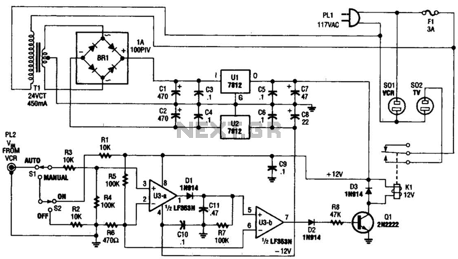
This circuit detects the video signal from the VCR. When the VCR is powered on, the video signal is amplified by U3A to drive Q1, which activates K1. This setup eliminates the need to manually turn on and off...
Many audio systems consist of separate units, where typically only the amplifier is equipped with a remote control receiver module for economic reasons. Control signals are then transmitted to other units using patch cables. For instance, the tuner and...
At half brightness, the lamp current is pulsed on and off by the voltage developed across the resistor and capacitor at the current-sense output. The current-sense output detects the lamp current. A basic pulse-width modulation (PWM) lamp-brightness control circuit...