
Telephone Line Controller
The circuit operates by monitoring the status of multiple telephones connected to a single telephone line. The primary component for sensing the line status is the optocoupler (IC1), which isolates the control circuit from the telephone line. When the telephone is in use, the voltage drops significantly, triggering the photodiode within the optocoupler, which then activates the transistor. This action changes the state of the logic gates in IC2, controlling the relay (RL1) that can activate various appliances or indicators.
The relay contacts can be used to switch devices such as lights or audio equipment, allowing for a versatile application of the circuit. The inclusion of a delay circuit ensures that transient signals do not cause unintended activation of the relay, enhancing the reliability of the system. The choice of resistor values for R4 determines the sensitivity and responsiveness of the relay activation, providing flexibility based on the specific application requirements.
The circuit is powered by a regulated +12V supply derived from a transformer (T1) and a voltage regulator (IC3), ensuring stable operation despite variations in the input voltage. The use of standard components such as resistors, capacitors, diodes, and relays makes this circuit easy to assemble and integrate into existing systems. Proper consideration should be given to the ratings of the components to ensure they can handle the expected voltages and currents during operation. A very simple circuit, that will find application in the case where you have a lot of telephones installed on a telephone line and would want to know if somebody of them is open. Thus you will not be off any discussion. Simultaneously it can cut the certain sound from stereo amplifier that are in high volume, the sound of some television or turn on some light the night when it ring the telephone and needs him you raise.
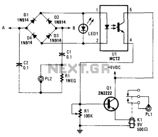
Exists a pair of free contacts of RL1 that connects to the J2, which you can use connecting there any appliance you want. The telephone line connected in the J1, with what polarity you wants. When the telephone is closed then the line voltage is roughly, 48-50Vdc. This voltage turn on the photodiode and this, the transistor of IC1, which it simultaneously isolates, the circuit from the telephone line. The phototransistor in IC1 are now in situation ON, the input of IC2A are LOW [L] and output HIGH [H].
Ignoring for little the circuit of delay D6, R4, R5, C1, the IC2B input, are also this HIGH hence the output are LOW, transistor Q1 are OFF and the RL1 are deactivate. When the telephone earphone is raised, then the telephone voltage line fall in 6-10Vdc. All the previous situation is reversed also the RL1, turn on. The telephones that use for dial choice, disk or pulse system, can they open and close the RL1 at the duration of choice.
With delay network, that exist between in gates IC2A and in the IC2B, we delay the situation changes in the input of IC2B, ensuring thus stability in the operation of RL1. If the R4=100K then the RL1 is activated when the telephone ring or when the earphone is raised. On the contrary if the R4=1M, then the RL1 is activated only when the earphone is raised. The circuit supply becomes with a simple regulation circuit, in + 12V. Part List R1-2=36Kohm D1....4=1N4002 RL1=12Vdc 2X2 relay R3=100Kohm D5=1N5252 [24V 0.5W Zener] J1-4=2pin connector 2.54mm step R4=100Kohm or 1Mohm *See text D6-7=1N4148 J2=6pin connector 5mm step R5=2.2Mohm D8....11=1N4002 J3=2pin connector 5mm step R6=3.3Kohm D12=Red Led 3 or 5mm F1=Fuse 500mA [5x20mm] R7=1Kohm IC1=4N25 optocupler PCB mount for Fuse C1=100 or 220nF 100V MKT IC2=4011B C2=1000uF 25V IC3=7812 [1A] *All Resistors is 1/2W 5% C3-4=100nF 100V Q1=BD139 or BD679 C5=4.7uF 16V T1=12Vac 500ma tranformer for pcb
🔗 External reference
Related Circuits
During summer nights, the temperature is initially quite high. As time passes, the temperature starts dropping. Also, after a person falls asleep, the metabolic rate of one's body decreases. Thus, initially the fan/cooler needs to be run at full...

Efforts were made to minimize the number of wire jumpers on this board, but space constraints arose due to the integration of the microcontroller and motor driver on a single board. The design would have been cleaner without the...
This RS-232 type line receiver is designed to drive CMOS logic and incorporates a Schmitt-trigger feedback network that provides approximately 1-V input hysteresis, enhancing noise immunity. A potential issue in an interface connecting two devices, each connected to different...
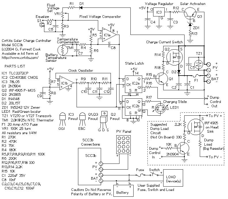
SCC3 12 Volt 20 Amp Solar Charge Controller. A kit with the circuit board and parts for this circuit is available from CirKits. SCC3 - 12 Volt 20 Amp Solar Charge Controller (C) G. Forrest Cook June. The SCC3 Solar...
This circuit operates on the ringing voltage of the telephone to trigger a tape recorder to record messages. It can be made to latch using extra contacts if the tape recorder requires a constant-contact closure. The circuit utilizes the ringing...
An alphanumeric low-cost LCD display is essential for many small and large projects to display various types of information. The Hitachi HD44780 chipset-based 16x2 character LCD is very affordable and easily available in the local market. This project covers...
Warning: include(partials/cookie-banner.php): Failed to open stream: Permission denied in /var/www/html/nextgr/view-circuit.php on line 713
Warning: include(): Failed opening 'partials/cookie-banner.php' for inclusion (include_path='.:/usr/share/php') in /var/www/html/nextgr/view-circuit.php on line 713