
Simple Lamp Dimmer Fan Regulator
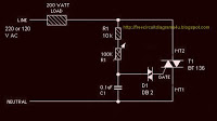
This circuit utilizes a Triac for controlling the power delivered to a load by varying the firing angle. The key components include resistors R1, R2, and capacitor C2, which form a timing network that influences the phase angle at which the Triac is triggered. The variable resistor R1 allows for fine-tuning of the firing angle, which directly correlates to the amount of power delivered to the load. This is achieved by adjusting how long the Triac remains in the conductive state during each AC cycle.
The firing mechanism is facilitated by Diac D1, which ensures that the Triac T1 is turned on at the appropriate moment in the AC waveform. When the voltage across the Diac reaches its breakdown voltage, it conducts, sending a pulse to the gate of the Triac, thus initiating conduction. The timing of this pulse is controlled by the RC timing circuit formed by R1, R2, and C2. As R1 is varied, the delay before the Diac triggers the Triac changes, effectively altering the power delivered to the load.
For assembly, it is crucial to use a quality PCB or a common board to ensure reliability and safety. The circuit is designed to handle loads up to 200 Watts, making it suitable for various applications such as lighting and fan control. However, for loads exceeding this limit, a Triac with a higher voltage and current rating should be utilized to prevent damage and ensure safe operation.
It is important to note that all components in this circuit are live during operation, presenting a risk of electric shock. Proper precautions should be taken when working with the circuit, including ensuring that the power is disconnected during assembly and maintenance. Proper insulation and safe handling practices are essential to mitigate any hazards associated with the high voltages present in the circuit.The circuit works by varying the firing angle of the Triac. Resistors R1, R2 and capacitor C2 are associated with this. The firing angle can be varied by varying the value of any of these components. Here R1 is selected as the variable element. By varying the value of R1 the firing angle of Triac changes (in simple words, how much time should Triac conduct) changes. This directly varies the load power, since load is driven by Triac. The firing pulses are given to the gate of Triac T1 using Diac D1. Assemble the circuit on a good quality PCB or common board. The load whether lamp, fan or any thing, should be less than 200 Watts. To connect higher loads replace the Triac BT 136 with a higher Watt capacity Triac. All parts of the circuit are active with potential shock hazard. So be careful. 🔗 External reference
Related Circuits
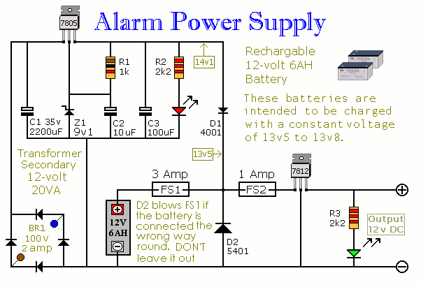
This power supply is designed for the Modular Burglar Alarm but is suitable for various applications. It delivers a 12-volt output with a maximum current of 1 amp. In case of a mains failure, the backup battery activates immediately,...
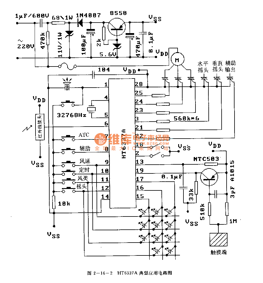
The HT6337 is an infrared remote control receiving decoder circuit specifically designed for electric fan applications. It is housed in a 28-pin dual-row DIP package, with the compatible model being HT12C. The HT6337 is part of a series of...
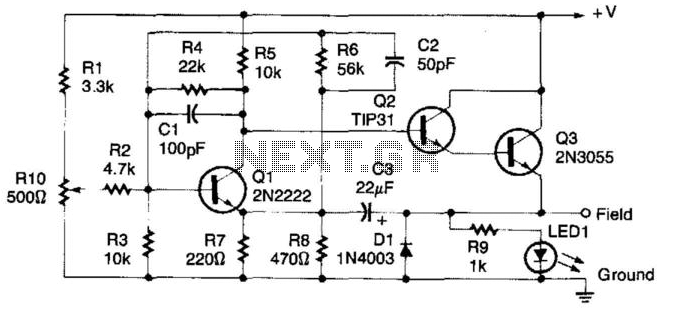
This regulator circuit can be used on an alternator that has one field terminal grounded. When the input voltage becomes too high, Q1 conducts, and the base of Q2 is driven toward ground, reducing the voltage fed to Q3....
Most dimmers utilize pulse width modulation (PWM) to regulate the power supplied to the lamp. Those that include a switch faceplate manage the firing angle of a Triac on the 240V mains side. While these dimmers work effectively with...
This line voltage power controller connects a DC control voltage or microprocessor logic output to an AC load. By adding a filter capacitor to the input resistors, the circuit can be controlled by a duty-cycle modulated square wave with...
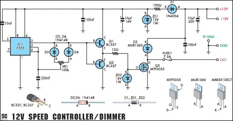
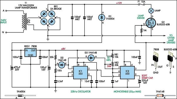
This circuit serves as a speed controller for a 12V motor with a continuous rating of up to 5A or as a dimmer for a 12V halogen or standard incandescent lamp rated up to 50W. It regulates power to...