
Voltage Regulator For Cars And Motorcycles
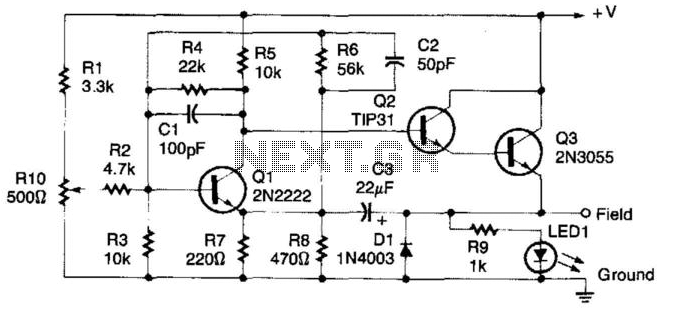
The described regulator circuit is designed to stabilize the output voltage of an alternator by controlling the excitation of its field winding. In this configuration, the alternator's field terminal is grounded, which allows for efficient regulation of the output voltage.
The operation begins with the input voltage (V) being monitored. When this voltage exceeds a predetermined threshold, transistor Q1 becomes conductive. This conduction effectively pulls the base of transistor Q2 towards ground potential. As a result, Q2 turns off, leading to a decrease in the base current to transistor Q3. Consequently, Q3 also reduces its conduction, which directly affects the voltage applied to the alternator's field winding.
By lowering the voltage to the field, the regulator circuit effectively reduces the magnetic field strength generated by the alternator. This action helps to prevent overvoltage conditions that could potentially damage the electrical components connected to the alternator or the alternator itself.
In summary, this regulator circuit is a critical component in automotive and industrial applications, ensuring that the alternator operates within safe voltage limits while maintaining optimal performance under varying load conditions. The use of transistors for voltage regulation allows for rapid response to changes in input voltage, providing a robust solution for voltage management in alternator systems. This regulator circuit can be used on an alternator that has one field terminal grounded. When + V (input) gets too high, Ql conducts, and the base of Q2 is driven toward ground, reducing the voltage fed to Q3. This lowers the voltage fed to the field of the alternator. 🔗 External reference
Related Circuits
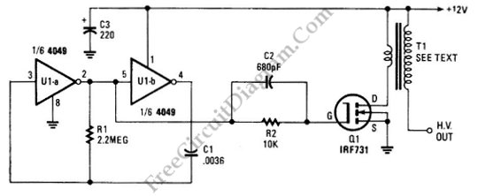
The schematic diagram below illustrates a circuit for a high voltage generator. This circuit employs a 4049 hex inverter as an oscillator, and it can be utilized for ignition purposes. The high voltage generator circuit is designed to convert a...
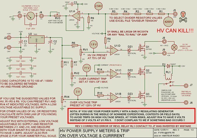
High voltage resistors for the high voltage divider are SFERNICE or PHILIPS type VR37 (3.5 kV - 0.4 W). They are not expensive (even if they are sold in quantities of 25 or 50 units), and it is always...
This device is a combination digital clock timer and solar panel charge controller designed to maintain a deep cycle battery charged by a solar panel. The timer output controls a 12-volt load for a 32-minute interval each day. The...
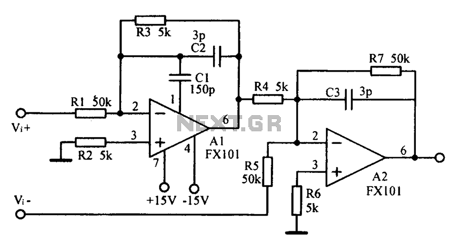
Common mode input voltage up to a difference of 100V enlarged circuit diagram. The circuit diagram described features a design capable of handling a common mode input voltage with a differential range of up to 100V. Such a configuration is...
The drawback of the circuit mentioned is that the operational amplifier (op-amp) supply is connected to the high voltage (HV) supply. Most op-amps are limited to approximately 30V for their supply voltage, which prevents the circuit from functioning with...
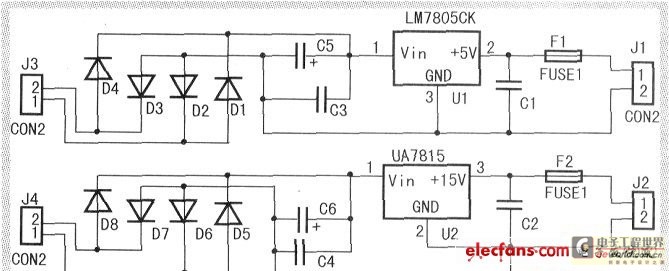
When the input voltage is between 198-242V, the average load current should be maintained at 0.5-1A, and the output voltage must remain at 15V with an error margin of less than 5%. The design and measurement of the stabilized...
Warning: include(partials/cookie-banner.php): Failed to open stream: Permission denied in /var/www/html/nextgr/view-circuit.php on line 713
Warning: include(): Failed opening 'partials/cookie-banner.php' for inclusion (include_path='.:/usr/share/php') in /var/www/html/nextgr/view-circuit.php on line 713