
TDA7262 stereo 20 watts audio amplifier circuit design
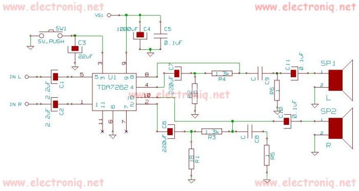
The TDA7262 is an integrated circuit designed for stereo audio amplification, capable of delivering up to 20 watts per channel. This amplifier circuit is suitable for various applications, including home audio systems, portable speakers, and other consumer electronics. The design utilizes the TDA7262's efficient architecture to provide high-quality sound output while minimizing power consumption and heat generation.
The circuit typically includes the TDA7262 IC, which features built-in short-circuit protection, thermal shutdown, and a mute function. The input stage can be configured to accept standard audio signals from various sources, such as smartphones, computers, or other audio devices. Capacitors and resistors are used to filter and stabilize the audio signals, ensuring optimal performance.
Power supply considerations are crucial in this design. A dual power supply configuration is often employed, with separate positive and negative voltage rails to maximize the amplifier's output capabilities. Decoupling capacitors should be placed close to the power pins of the TDA7262 to reduce noise and improve stability.
Output stages typically include speaker protection circuits to prevent DC offset and ensure that the connected speakers are not damaged during operation. Additionally, heat sinks may be required to dissipate heat generated by the amplifier during prolonged use, particularly when operating at higher output levels.
Overall, the TDA7262 stereo audio amplifier circuit is a robust solution for delivering high-quality audio in a compact and efficient package, making it a popular choice for audio enthusiasts and engineers alike.TDA7262 stereo 20 watts audio amplifier circuit design electronic project 🔗 External reference
Related Circuits
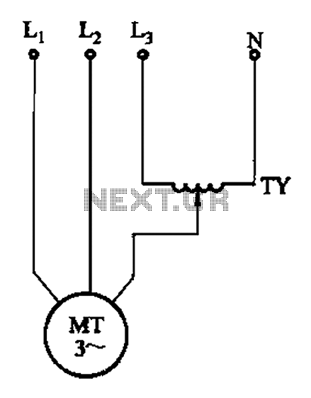
The circuit illustrated in Figure 3-175 features a regulator connected between one phase and neutral. It is designed for use with a 380V torque motor. This method offers advantages over the serious line imbalance approach, resulting in improved operating...
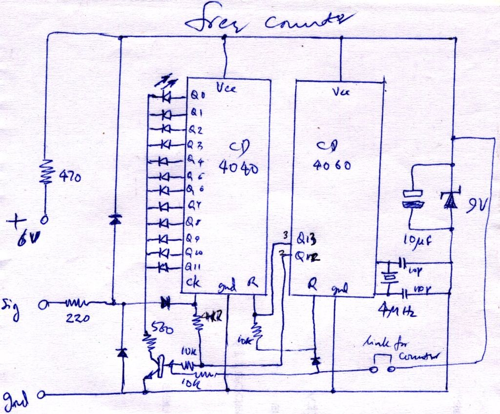
The construction is nearly complete, and a circuit diagram has been created. The design has been finalized and documented on paper. The circuit diagram represents a critical stage in the development of an electronic project, serving as a blueprint for...
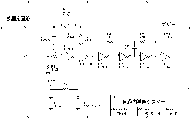
Continuity tester to check continuity in the circuit (Insakittochekka) is. The continuity check over the circuit board wiring that can be checked at a lower voltage semiconductors do not conduct contained in the circuit, you can just check the...
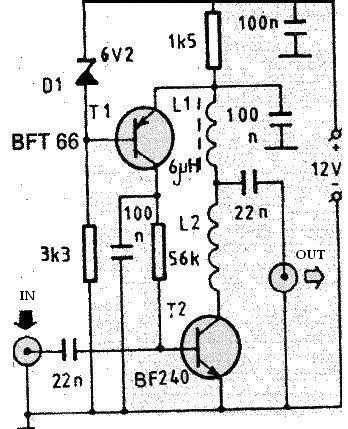
The PCB of this circuit should be positioned close to the antenna within a compact metallic enclosure. This VHF antenna circuit requires a 12 volts DC power supply, which can be sourced from a 12-volt battery, as the current...
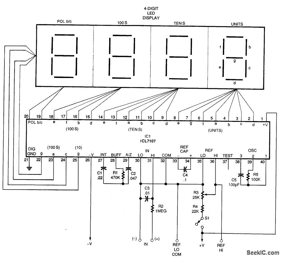
A basic digital voltmeter circuit utilizing the Harris Semiconductor ICL7107 is presented. It operates within a 2-V range. Calibration involves applying a known voltage of 1.2 V to the input and adjusting resistor R3 to achieve an accurate reading...
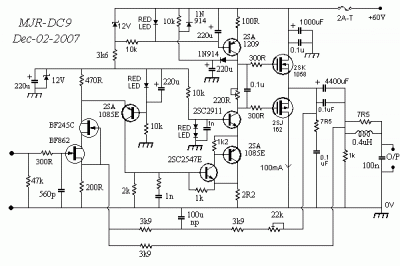
This circuit includes a 220µF capacitor and two diodes designed to slow down the switch-on process, thereby minimizing the output thump that occurs as the output capacitor charges through the speaker. While this feature is not essential and may...
Warning: include(partials/cookie-banner.php): Failed to open stream: Permission denied in /var/www/html/nextgr/view-circuit.php on line 713
Warning: include(): Failed opening 'partials/cookie-banner.php' for inclusion (include_path='.:/usr/share/php') in /var/www/html/nextgr/view-circuit.php on line 713