
Simple Logic Probe
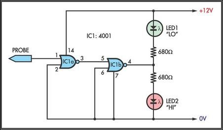
The logic probe circuit utilizes two NOR gates, configured in a way that allows for effective detection of digital signals. The circuit is powered by a 12V supply, which ensures that both LEDs are normally on when no input signal is detected. This is achieved through the forward biasing of the LEDs, allowing them to illuminate continuously in the absence of input.
When a logic high signal is applied to the probe, the output of the first NOR gate (IC1a) transitions to a low state. This change causes the output of the second NOR gate (IC1b) to transition to a high state. As a result, LED1, which is connected to the output of IC1b, turns off, while LED2, which is connected to the output of IC1a, is activated due to forward biasing. This dual LED indication provides a clear visual representation of the logic state.
In contrast, when a logic low signal is detected at the probe, IC1b's output goes low, resulting in LED1 turning on and LED2 turning off. This mechanism allows the probe to provide accurate feedback on the logic levels present at its input, effectively distinguishing between high and low signals.
The design of this logic probe is particularly beneficial for testing digital circuits, as it can accurately respond to pulse trains, making it a versatile tool for engineers and technicians. The simplicity of the circuit, combined with the clarity of LED indications, enhances its usability in various electronic applications.This simple logic probe has both LEDs on with no signal at the input but due to the nor gates connected to the probe, indicates correctly when a high or low signal is present. It also works correctly for pulse trains. Normally both LEDs are forward biased and therefore on, powered by the 12V supply. When a logic high is present at the probe, IC 1a`s output goes low sending IC1b`s output high. This turns off LED1 but forward-biases (and turns on) LED2. Conversely, a logic low at the probe will send IC1b low, turning LED1 on and LED2 off. 🔗 External reference
Related Circuits
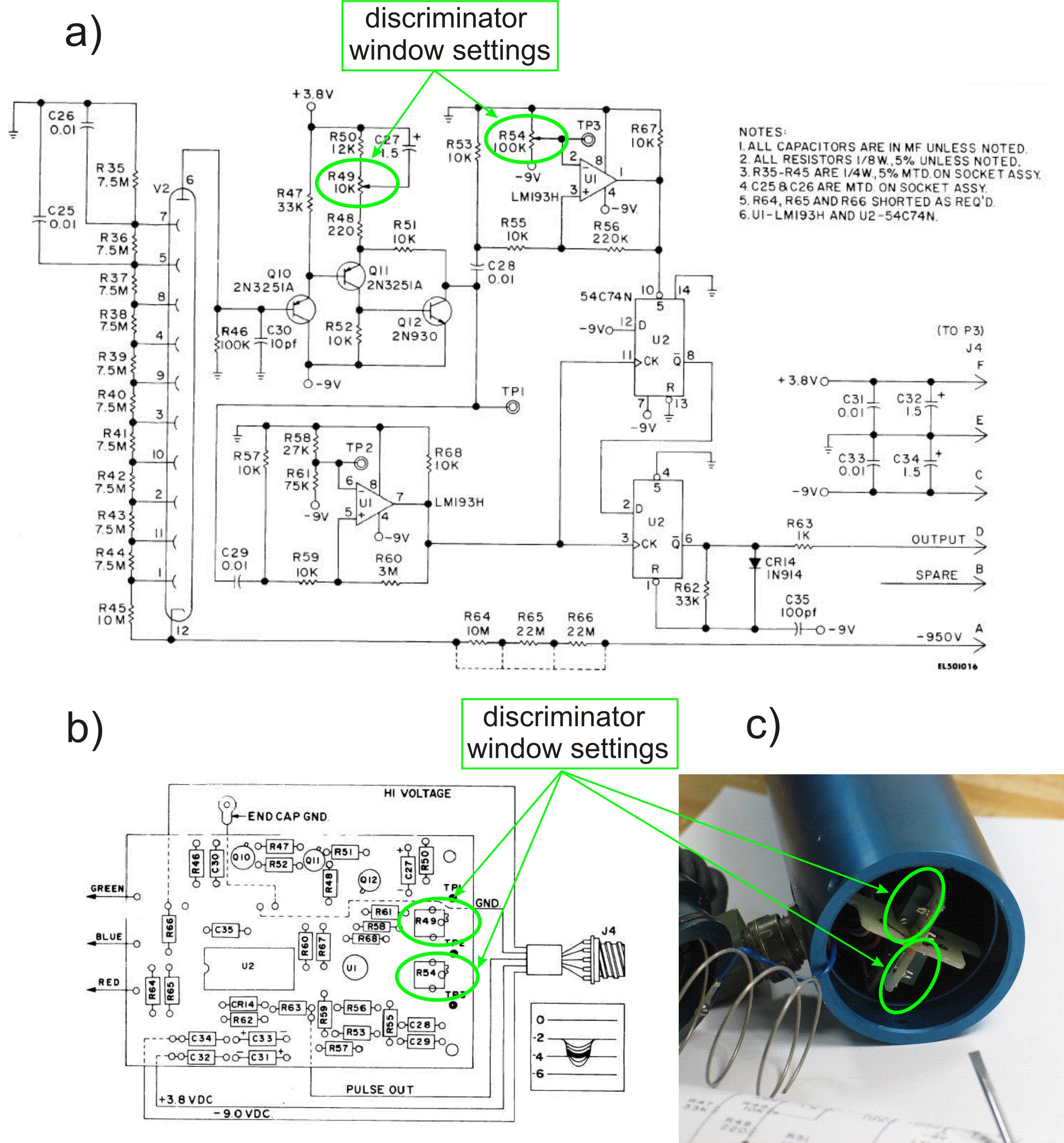
This PDF file presents the schematic diagram of a custom-built circuit designed to drive the PDR-56 probe. A JKL BXA-12579 inverter, typically used for powering cold-cathode fluorescent lamps, serves as the high-voltage power supply. The BXA-12579 generates 1,500 VAC...
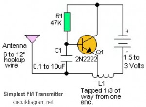
This is likely the simplest radio transmitter available, consisting of five components and capable of being assembled in a compact space. It is suitable for science fair projects or other science-related endeavors where short-range transmission is beneficial. The device...
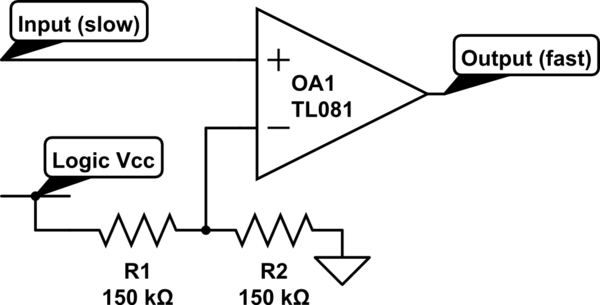
Invert a signal to drive FETs with rapid rise and fall times. It was suggested to use an inverter (not a chip) instead of logic chips, which are designed to be either fully ON or OFF. The individual has...
The output cable from my 20 MHz function/sweep generator dangled over the side of the workbench, the alligator clip hovering over the floor. Deeply engrossed in a project, I moved the power strip on the floor a little closer...
A logic indicator circuit, also known as a logic probe, is utilized to identify the logic level at any point within a logic circuit. The indicator can be visual, employing components such as LEDs, LCDs, or seven-segment displays. The logic...
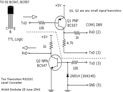
When connecting a microcontroller project to a COM port on a PC, an RS-232 converter is required. Various chips can accomplish this task, such as the MAX232 and DS275. However, for a simple and cost-effective RS-232 converter, the following...
Warning: include(partials/cookie-banner.php): Failed to open stream: Permission denied in /var/www/html/nextgr/view-circuit.php on line 713
Warning: include(): Failed opening 'partials/cookie-banner.php' for inclusion (include_path='.:/usr/share/php') in /var/www/html/nextgr/view-circuit.php on line 713