
simple low cost digital code lock

A key characteristic of this electronic code lock is its operation in monostable mode; once triggered, the output becomes high and remains so for a predetermined duration, determined by the timing components, before returning to a low quiescent state. The circuit employs a timer IC 555, which is low-cost and readily available. Pin 2 of the IC serves as the triggering input; when this pin is held below one-third of the supply voltage, the output transitions to a high state. Conversely, the threshold pin 6, when elevated above two-thirds of the supply voltage, drives the output to a low state. A low-going pulse applied to the reset pin 4 brings the output at pin 3 back to the quiescent low level, necessitating that this reset pin be held high for normal operation of the IC.
To unlock the system, switches SA-SC, S1-S8, and S3-S4 must be pressed in that order. When switches SA and SC are pressed simultaneously, capacitor C3 charges through a potential divider formed by resistors R3 and R4. Upon releasing these switches, capacitor C3 begins to discharge through resistor R4. The values of capacitor C3 and resistor R4 are selected such that complete discharge occurs in approximately five seconds. If switches S1 and S8 are pressed within five seconds after releasing switches SA and SC, pin 2 is pulled to ground, triggering the IC 555. This action initiates the charging of capacitor C1 through resistor R1, resulting in the output at pin 3 going high for five seconds, corresponding to the time required for capacitor C1 to charge to the threshold voltage, calculated using the formula T = 1.1 R1 x C1 seconds.
The switches also connect a relay to output pin 3, which energizes the relay. The relay contacts close, activating a solenoid that pulls in the latch, thereby unlocking the mechanism. Additional switches are connected between reset pin 4 and ground; pressing any of these switches resets the IC, returning the output to its low quiescent state. The likelihood of these reset switches being pressed increases when a code breaker attempts to access the lock.
This digital code lock circuit exemplifies a practical application of timer ICs in security systems, providing a balance of simplicity, cost-effectiveness, and reliability in unlocking mechanisms. The design ensures a clear sequence of operations, enhancing security while allowing for a straightforward user interface.In those circuits a set of switches (conforming to code) are pressed one by one within the specified time to open the lock. In some other circuits, custom-built ICs are used and positive and negative logic pulses are keyed in sequence as per the code by two switches to open the lock.
A low-cost digital code lock circuit is presented in this article. Here the keying-in code is rather unique. Six switches are to be pressed to open the lock, but only two switches at a time. Thus a total of three sets of switches have to be pressed in a particular sequence. (Of these three sets, one set is repeated. ) The salient features of this circuit are: An essential property of thiselectronic code lockis that it works in monostable mode, i. e. once triggered, the output becomes high and remains so for a period of time, governed by the timing components, before returing to the quiescent low state.
In this circuit, timer IC 555 with 8 pins is used. The IC is inexpensive and easily available. Its pin 2 is the triggering input pin which, when held below 1/3 of the sup-ply voltage, drives the output to high state. The threshold pin 6, when held higher than 2/3 of the supply voltage, drives the output to low state.
By applying a low-going pulse to the reset pin 4, the output at pin 3 can be brought to the quiescent low level. Thus the reset pin 4 should be held high for normal operation of the IC. Three sets of switches SA-SC, S1-S8 and S3-S4 are pressed, in that order, to open the lock. On pressing the switches SA and SC simultaneously, capacitor C3 charges through the potential divider comprising resistors R3 and R4, and on releasing these two switches, capacitor C3 starts discharging through resistor R4.
Capacitor C3 and resistor R4 are so selected that it takes about five seconds to fully discharge C3. Depressing switches S1 and S8 in unison, within five seconds of releasing the switches SA and SC, pulls pin 2 to ground and IC 555 is triggered. The capacitor C1 starts charging through resistor R1. As a result, the output (pin 3) goes high for five seconds (i. e. the charging time T of the capacitor C1 to the threshold voltage, which is calculated by the relation T=1.
1 R1 x C1 seconds). These switches connect the relay to out-put pin 3 and the relay is energised. The contacts of the relay close and the solenoid pulls in the latch (forming part of a lock) and the lock opens. The remaining switches are connected between reset pin 4 and ground. If any one of these switches is pressed, the IC is re-set and the output goes to its quiescent low state.
Possibilities of pressing these reset switches are more when a code breaker tries to open the lock. 🔗 External reference
Related Circuits
After the battery is connected, the movement of the touch stick activates the light source, which illuminates the photosensitive tube and generates a light current. This triggers the first level 3DG6 to turn on, allowing the emitter to output...

The goal of Advanced Digital Electronics courses is to connect basic logic gates (combinational circuits) with technical subjects related to binary counter topologies (both Asynchronous and Synchronous), shift registers, memory, and Digital Signal Processors (DSP), which are categorized as...

An FM and AM transmitter integrated into a compact device utilizing the CD4001 integrated circuit. It broadcasts at 20 MHz for AM and 100 MHz for FM. The described transmitter combines both Frequency Modulation (FM) and Amplitude Modulation (AM) capabilities...
S1 is a power switch. U2 drives counter U3 by producing a pulse when S2 is depressed. U4 and DISP1 read the count of counter IC U3. S3 is a reset to zero switch. The counter is a basic...
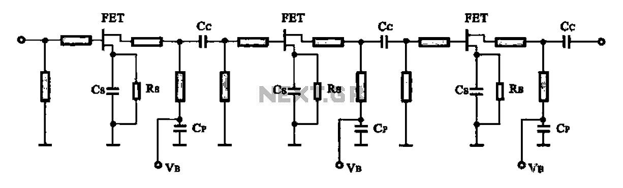
In general high-frequency circuits within the microwave band, microstrip circuits are utilized to achieve input and output matching as well as frequency-selective amplifier circuits. A figure illustrates a monolithic microwave integrated circuit low-noise amplifier. Additionally, a downconverter mixer includes...
The circuit amplifier and attenuator control video detector consists of a composition for the synchronization channel. The synchronization interval is where the gain circuit is increased. The described circuit involves an amplifier and an attenuator that work together to control...