
Simple Under-Voltage Cut-Out
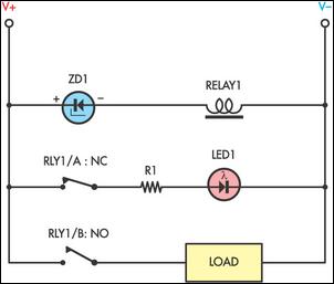
Sensitive low-current relay coils are designed to function effectively at specified voltage ratings; however, they may exhibit erratic behavior when operating at lower-than-expected supply voltages. This issue can lead to unreliable performance in various applications, particularly in systems where precise operation is critical. To mitigate this problem, the incorporation of a zener diode in series with the relay coil is a recommended approach.
The zener diode serves as a voltage clamping device, effectively limiting the voltage applied to the relay coil. When the supply voltage exceeds the zener breakdown voltage, the diode conducts, thereby reducing the voltage across the relay coil. This results in the relay dropping out at a lower voltage threshold, which can enhance the stability of the system under low-voltage conditions.
Furthermore, integrating a light-emitting diode (LED) into the circuit can provide a visual indication of the relay's status. If spare "normally closed" contacts are available on the relay, the LED can be wired in such a way that it illuminates when the relay is in the dropout state. This visual feedback can be invaluable for troubleshooting and monitoring system performance, ensuring that operators are aware of the relay's operational status at all times.
The design considerations for this circuit must include the selection of an appropriate zener diode that matches the specific voltage requirements of the relay coil. Additionally, the LED should be chosen based on the desired brightness and the forward voltage drop, ensuring that it operates efficiently within the circuit without adversely affecting the relay's performance. Overall, this configuration enhances the reliability and functionality of sensitive low-current relay applications.Sensitive low-current relay coils often operate at much lower voltages than their typical ratings. This can be undesirable in some applications, where low supply voltages can result in erratic system behaviour. In some instances, this problem could be overcome simply by inserting an appropriate value zener diode in series with the relay coil.
This reduces the voltage seen by the relay coil, so causing it to drop out earlier. If desired, a LED could be included when a spare set of "normally closed" contacts are available to indicate relay dropout. 🔗 External reference
Related Circuits
Trimming is straightforward when matched NPN transistors are utilized for Q1 and Q2, along with 1% tolerance resistors for R6 to R11. A dual trace oscilloscope, digital voltmeter (DVM), and sine wave generator are required for this process. Although...
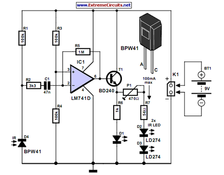
Many consumer electronic devices such as television sets, VCRs, CD players, and DVD players utilize infrared remote control technology. In certain situations, it is beneficial to extend the range of these remote controls. Infrared (IR) remote controls operate by emitting...
This is a circuit diagram for a fuse monitor circuit indicator. This very simple circuit utilizes only two components: a single resistor and an LED. This circuit provides a visual indication when the fuse has blown. LED1 typically remains...
The above pictured schematic diagram is just a standard constant current model with a added current limiter, consisting of Q1, R1, and R4. The moment too much current is flowing biases Q1 and drops the output voltage. The output...
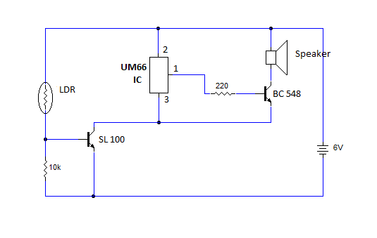
This article provides instructions for creating a light-sensitive morning alarm circuit. The circuit utilizes an LDR (Light Dependent Resistor) or photoresistor to detect morning light, which triggers the alarm section. When light is detected, the circuit produces a melodious...

To create a telephone ring monitor, it is sufficient to connect a resistor in series with a bulb and plug it into a main outlet. The resistance value of this resistor may vary depending on the type of bulb...
Warning: include(partials/cookie-banner.php): Failed to open stream: Permission denied in /var/www/html/nextgr/view-circuit.php on line 713
Warning: include(): Failed opening 'partials/cookie-banner.php' for inclusion (include_path='.:/usr/share/php') in /var/www/html/nextgr/view-circuit.php on line 713