
Simple Mobile Phone Battery Charger
The circuit operates by first transforming the high-voltage AC mains into a lower AC voltage suitable for charging applications. The transformer X1 is key to this process, stepping down the voltage to 9V AC. The subsequent rectification stage employs a bridge rectifier configuration using diodes D1 to D4, which efficiently converts the AC voltage into a pulsating DC voltage. The positive output from the rectifier is directly connected to the output terminal of the charger, while the negative side is routed through resistor R2, which serves to limit the current flowing into the load, preventing potential damage from excessive current.
LED2 is incorporated into the design as a power indicator, providing visual confirmation that the charger is operational. Resistor R1 is used to limit the current through LED2, ensuring it operates within safe parameters. Additionally, LED3 serves as a charging status indicator, which is illuminated when the charging process is active. The voltage drop across R2 during charging activates LED3 through resistor R3, providing feedback to the user regarding the charging state.
The LM78xx voltage regulator is employed to maintain a consistent and stable output voltage, which is crucial for safely charging batteries. This regulator can be adjusted to suit various charging requirements, making the circuit versatile for different types of battery chemistries, particularly NiCAD batteries. The design supports both single-cell and multi-cell configurations, allowing for flexibility in battery arrangements, with a maximum permissible voltage of 18V for the connected batteries.
Power transistors Q1 and Q2 are utilized as series regulators, enhancing the circuit's ability to handle varying load conditions while maintaining output stability. The inclusion of a battery level indicator circuit provides valuable information regarding the battery's charge status, typically represented in a user-friendly format such as dots or bars.
The mobile charger circuit also features an anti-theft mechanism, producing a loud chirping sound when unauthorized removal of the mobile phone is attempted. This added functionality enhances the security of the device, making it suitable for use in public or shared environments.
For applications involving solar power, the solar-powered mobile phone battery charger is designed to efficiently charge batteries from a lower voltage source, with careful consideration to avoid using it for batteries that cannot accept the generated voltage from the solar panel. The car battery charger circuit is designed with safety features to prevent overcharging, utilizing a feedback control mechanism to monitor and regulate the charging process, thus preserving the longevity of the battery.The 220-240V AC mains source is stepped down to 9V AC by transformer X1. The transformer output is rectified by diodes D1 through D4 connected in bridge configuration and the positive DC source is straightly wired to the charger`s output contact, while the negative terminal is connected through current limiting resistor R2. LED2 operates as being a power indicator with resistor R1 serving as the current limiter and LED3 signifies the charging status. While in the charging period, about 3 volts drop happens across resistor R2, which switches on LED3 through resistor R3.
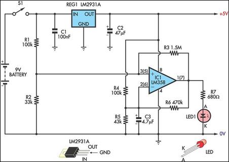
The following diagram is a simple mobile phone battery charger circuit. The design is simple, easy to build and inexpensive. It use LM78xx regulator to make regulated and stable output voltage. Mobile phone chargers offered in the marketplace are quite expensive. The circuit shown right here shows up as a low-cost option to charge cell. This battery charger circuit is regulated and adjustable to make this circuit able to charge the mosto NiCAD battery. This circuit will work for single cell or multi battery cell which connected with series/parallel connection.
The maximum voltage of the batteries should be 18V maximum. Power transistors Q1 and Q2 are connected as series regulators. Here the circuit diagram of simple and easy made battery level indicator. In general, in mobile phones, the battery levels is displayed in dot or bar style. This helps you to effortlessly acknowledge the battery level. On this page we provide a circuit that helps you to recognize the battery level of a instrument from. This is the cell phone shield circuit which can be used as mobile charger. Give protection to your cell phone from unexpected use or theft working with this easy circuit. It is able to produce a loud chirping sound when someone tries to take away the mobile handset. The added function is that the circuit. This is the schematic diagram of solar powered mobile phone battery charger. The circuit is designed to charge the battery from a source with a lower voltage. Do not use it to charge the battery with the same or lower voltage than the voltage which is generated by the solar panel.
For proper operation of. Here is a simple and easy to build circuit diagram of a 12V car battery charger: The above circuit claimed have ability to prevent battery overcharge that make electrolyte lost due to evaporation. This circuit will eliminate the problems by monitoring the battery`s condition of charge through its retroactive control circuit by applying a high.
🔗 External reference
Related Circuits
The shunt-feedback configuration facilitates the straightforward integration of frequency-dependent networks, enabling a functional and discreet switchable tilt control (optional). When SW1 is in the first position, a gentle shelving bass boost and treble attenuation occur. The central position of...
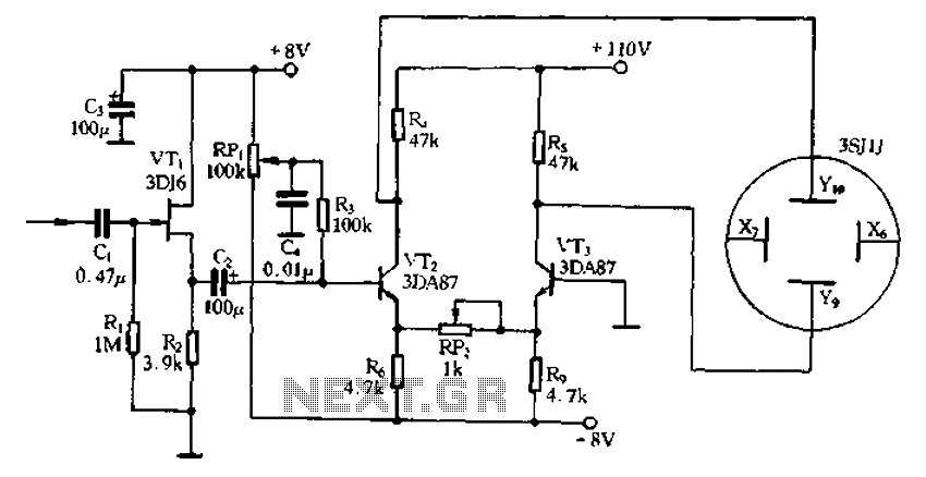
Application of the differential amplifier circuit in a simple small oscilloscope. The differential amplifier circuit is a crucial component in the design of a simple small oscilloscope. This circuit is designed to amplify the difference between two input voltage signals...
This circuit indicates the remaining battery life by varying the duty cycle and flash rate of an LED as the battery voltage decreases. It indicates five battery conditions: (1) a steady glow indicates that the battery is healthy; (2)...
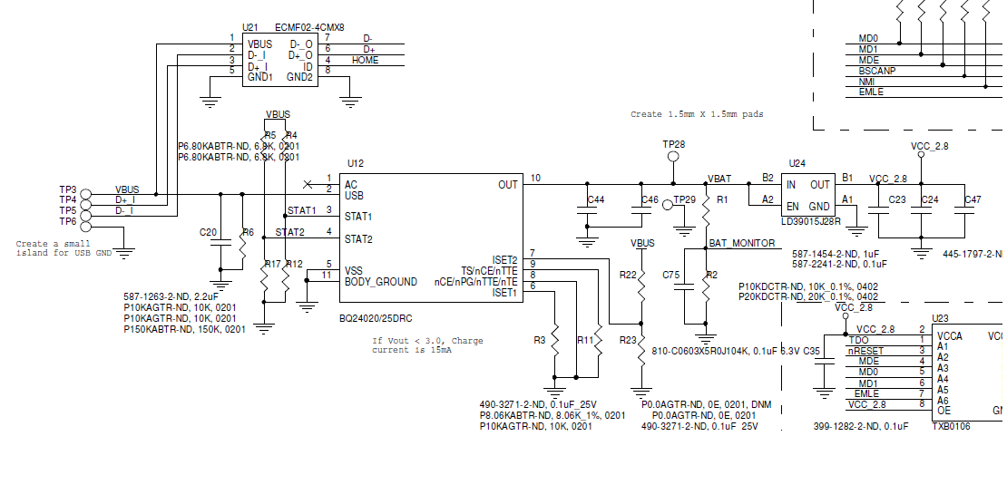
A BQ24020 charger IC is being utilized to charge a 120mAh Li-ion battery with a set charge current of approximately 100mA. The circuit schematic has been provided. The issue encountered is that the STAT1 and STAT2 signals indicate the...
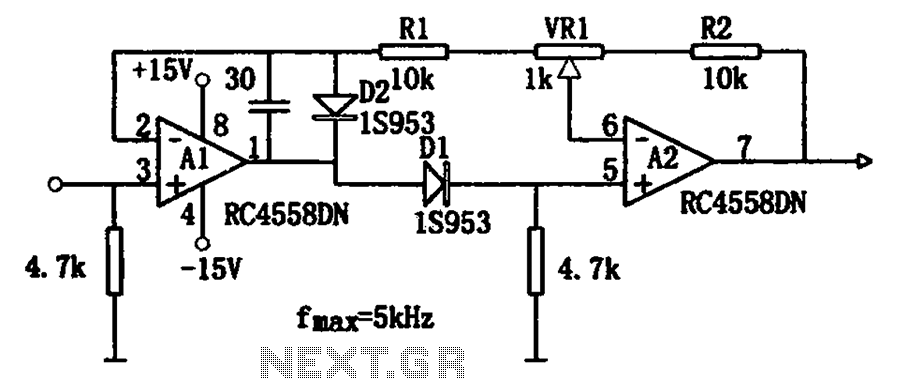
The circuit illustrates a simple method for adjusting the high input impedance of a double wave linear detector. It employs an operational amplifier configured with a negative feedback loop to compensate for the non-linear behavior of the diode used...

A motorcycle or boat battery that is not needed over the winter is typically charged before being stored for the season, during which it remains unused for several months. This inactivity can lead to the accumulation of lead sludge,...