
Simple NiCd Battery Charger
The proposed NiCd charger circuit utilizes an LM317 or a 78xx series voltage regulator to provide a stable output voltage suitable for charging nickel-cadmium batteries. The circuit design is straightforward, allowing for the use of commonly found components, which makes it cost-effective and accessible for hobbyists and engineers alike.
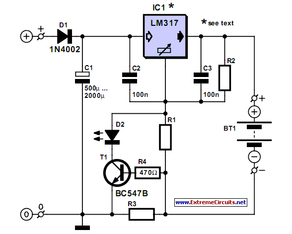
The primary function of the voltage regulator is to maintain a constant voltage level while the current flowing into the battery is managed by a current limiting resistor, R3. This resistor is critical in preventing overcurrent conditions that could lead to battery damage or reduced lifespan. The value of R3 should be chosen based on the desired charging current, which typically ranges from 0.1C to 0.5C of the battery's capacity.
In addition to R3, the circuit may include capacitors for input and output stabilization, ensuring that the voltage regulator operates efficiently and that the output voltage remains stable during the charging process. A diode may also be implemented in parallel with the battery to prevent reverse current flow when the charger is disconnected.
Care should be taken to ensure proper heat dissipation from the voltage regulator, as it may generate significant heat during operation, especially when charging larger capacity batteries. A heatsink may be required to maintain safe operating temperatures.
Overall, this simple NiCd charger design is effective for charging nickel-cadmium batteries while utilizing minimal components, making it an excellent project for those looking to create a functional and reliable charging solution.A simple NiCd charger can be built using junk box components and an inexpensive LM317 or 78xx voltage regulator. Using a current limiter composed of R3.. 🔗 External reference
Related Circuits

If a lead-acid battery is not used for an extended period, it experiences self-discharge at a rate of 4% per week at 27 degrees Celsius. For instance, a 125 Ah tubular battery discharges at a rate of 5 Amps...
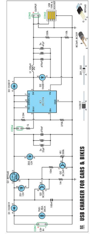
Seeking an efficient USB charger capable of operating from a 12V car battery? This unit operates at up to 89% efficiency and can charge USB devices effectively. This USB charger circuit is designed to convert a 12V car battery supply...
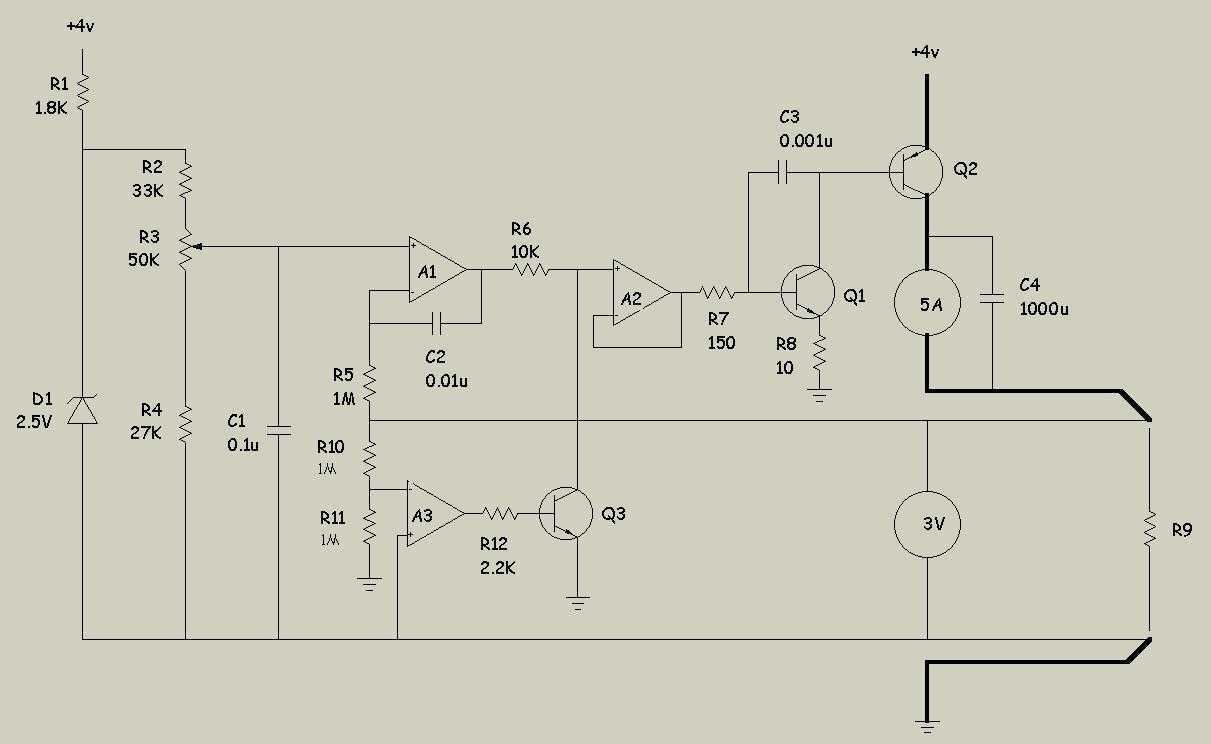
The driver circuit has 4 main sections: * the voltage definition, * the integrator, * the current booster, and * the foldover. The schematic is drawn so that higher voltages are toward the top and lower voltages are towards the bottom. D1 is...
This characterization circuit, along with a PC and specific software, accurately measures the complete discharge cycle of a rechargeable AA cell. The capacity and output resistance of the cell can be easily determined from the resulting curve of these...
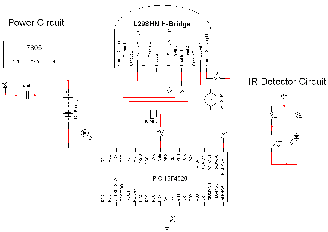
The simple motor optical encoder circuit is not particularly difficult; however, it requires careful verification to ensure all connections are correct before initial operation. The primary components utilized in the circuit include the 7805 voltage regulator, the PIC18F4520 microcontroller,...
Battery Indicator Circuit for the Caravan. This i-TRIXX circuit can prevent a lot of trouble for those who go on holiday in a caravan. It would be a significant damper on your holiday spirit when you are unprepared. The Battery...