
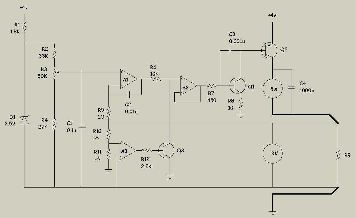
NiCads charger
* the voltage definition,
* the integrator,
* the current booster, and
* the foldover. The schematic is drawn so that higher voltages are toward the top and lower voltages are towards the bottom. D1 is a voltage reference, LM385BZ-2.5, that maintains a drop of 2.5 volts across its leads. Since B will be close to ground, there should be about 1.5 volts across R1 and about 0.8 mA of current, which is enough to keep D1 alive. The schematic above shows the overall control loop. The glowplug is represented by R9. Notice there are 2 connections at each end of the plug. The heavy lines represent heavy wire that carries the current to/from the plug. The thinner
The driver circuit is designed to control the operation of a glowplug, which is a resistive heating element used in diesel engines to aid cold starting. The circuit is divided into four distinct sections that each serve a specific function in the overall operation.
The voltage definition section utilizes the LM385BZ-2.5 voltage reference diode (D1), which ensures a stable 2.5V reference voltage necessary for the proper functioning of the circuit. This voltage reference is critical as it sets the baseline for the other components in the circuit. The resistor R1 is connected in series with the voltage reference to limit the current flowing through D1, ensuring that it operates within its specified range. The expected voltage drop across R1 is approximately 1.5V, leading to a current of around 0.8 mA, which is sufficient to maintain the operation of the voltage reference.
The integrator section processes the input signal and provides necessary feedback to maintain the desired operating conditions for the glowplug. This section typically includes an operational amplifier configured to integrate the voltage over time, ensuring that the output is a smooth, continuous signal rather than a pulsed one.
The current booster section is responsible for amplifying the current supplied to the glowplug. Given that the glowplug requires a significant amount of current to reach its operating temperature, this section is designed to handle higher currents without overheating or failing. It may include transistors or MOSFETs configured to switch larger currents while being controlled by the lower current signals from the previous sections.
Lastly, the foldover section serves as a protection mechanism, preventing the circuit from exceeding safe operational limits. It monitors the output current and voltage, ensuring that they remain within specified thresholds. If the current approaches unsafe levels, the foldover circuit will reduce the output, protecting both the glowplug and the driver circuit from damage.
The overall schematic is organized with higher voltage connections at the top and lower voltage connections at the bottom, which aids in understanding the flow of current through the circuit. The glowplug, represented by R9, is connected via heavy gauge wires, indicated by the thick lines in the schematic, to handle the significant current required for operation. The thinner lines represent other connections that may carry lower currents or signals. The careful design and arrangement of these components ensure the effective and safe operation of the glowplug driver circuit.The driver circuit (see the complete schematic) has 4 main sections: * the voltage definition, * the integrator, * the current booster, and * the foldover. The schematic is drawn so that higher voltages are toward the top and lower voltages are towards the bottom.
D1 is a voltage reference, LM385BZ-2.5 (you can get all these parts from Allied Electronics), that maintains a drop of 2.5 volts across its leads. Since B will be close to ground, there should be about 1.5 volts across R1 and about 0.8 mA of current, which is enough to keep D1 alive.
The (somewhat abstract) schematic above shows the overall control loop. The glowplug is represented by R9. Notice there are 2 connections at each end of the plug. The heavy lines represent heavy wire that carries the current to/from the plug. The thinner 🔗 External reference
Related Circuits

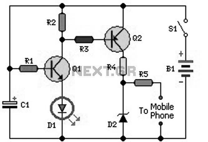
This circuit is designed as a low dropout charger using a MOSFET as the pass element; however, it does not incorporate current limiting. The circuit diagram illustrates a straightforward design. It utilizes Q3 and a Schottky diode to isolate...
Note first the battery to be treated at the center of the figure. It is connected to contacts of a relay. The diagram shows the relay at rest. Under these conditions the battery is in SHOCK. His pole -...
An ideal mobile charger utilizing 1.5-volt pen cells to charge mobile phones while traveling. This charger can replenish a cell phone battery three to four times in locations where AC power is unavailable. Most mobile phone batteries are rated...
Construct a straightforward DC to DC mobile battery charger to charge your mobile phone battery at any time and location by connecting it to a 12-volt source from a car or motorbike battery. This mobile battery charger circuit is designed...
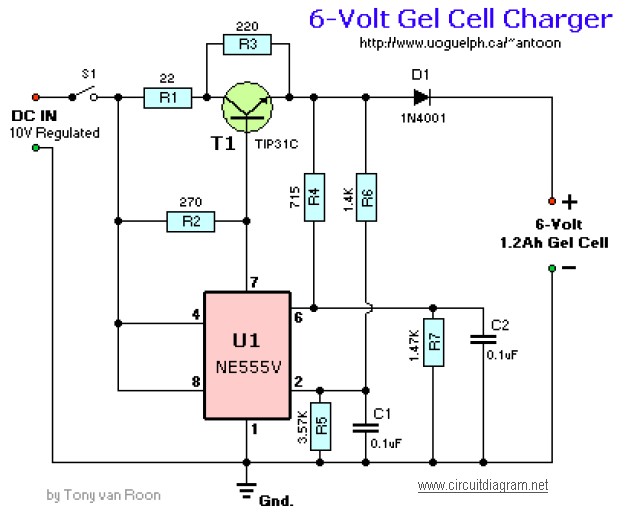
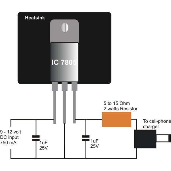
This circuit requires an adapted 10V DC power supply capable of delivering 2 Amps. It initiates the charging process at 240mA and automatically switches to a float charge (trickle charge) of 12mA when fully charged. The capacitors used should...
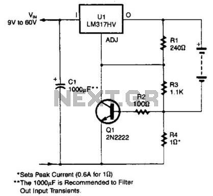
An LM317HV regulator is utilized as a current-limited charger. If the current through R4 exceeds 0.6 A, Q1 is activated, which pulls the ADJ terminal of the LM317HV to ground and reduces the battery charging current. The LM317HV is...