
Simple Op Amp Audio Amplifier

The circuit employs a CA3140 operational amplifier, which is known for its high input impedance and low output impedance, making it suitable for driving power transistors in audio applications. The complementary output stage utilizing Q1, Q2, and Q3 typically consists of NPN and PNP transistors configured to provide push-pull operation. This configuration enhances efficiency and allows for greater output power while minimizing distortion.
The output power capability of this circuit is contingent upon several factors, including the supply voltage, which in this case is specified at 30 volts, and the load impedance of the speaker connected to the output. Higher impedance speakers allow for greater power output, reaching up to 2 watts under ideal conditions.
Thermal management is critical in this design, as the power dissipation in transistors Q2 and Q3 must be carefully monitored to prevent overheating. Adequate heatsinking may be required to maintain safe operating temperatures, especially at higher output levels. The circuit may also include biasing resistors to set the quiescent current of the output stage, ensuring linear operation and minimizing crossover distortion.
Overall, this configuration is well-suited for audio amplification applications, providing a robust solution for driving speakers with sufficient power while maintaining sound quality. Proper attention to component selection and thermal management will enhance the reliability and performance of the circuit. A CA3140 drives a complementary output stage Ql, Q2, and Q3. Output power depends on supply voltage and limit s on dissipations of Q2 and Q3, but it can be 1 or 2 W with a higher impedance speaker and a 30-V supply.
Related Circuits
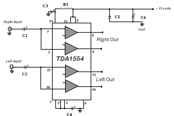
A 22 Watt stereo amplifier circuit diagram is presented. This circuit can be utilized for audio home amplifiers as well as car audio amplifiers. It features a straightforward design, is cost-effective, and is very easy to assemble, making it...
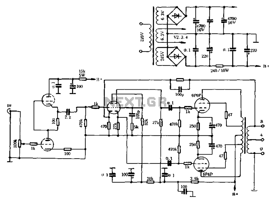
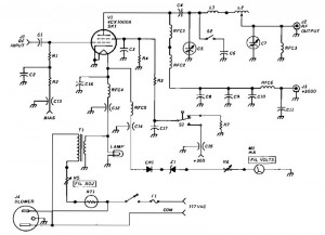
The self-generated bias amplifier tube is designed for each tube individually to alleviate the challenges faced by amateur conditions in paired amplifiers. It includes a separate DC filament power supply, which minimizes the risk of induced cross-linking and enhances...
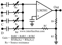
The circuit schematic below represents a method for designing an audio mixer. The active component is an LM318, although any operational amplifier could be used in its place. The circuit is a classic design for an operational amplifier summing...
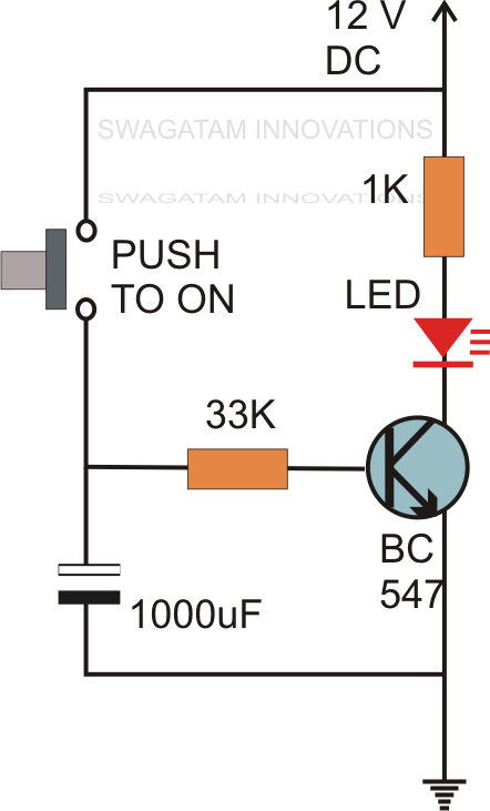
Without the specified delay, the circuit could malfunction or even sustain damage. A capacitor, which is a crucial component of the circuit, is positioned at the other end of the base resistor rather than directly connected to the base...
The SL517 is designed as an audio, RF, or infrared decoder circuit suitable for electronic toy applications. The internal circuitry consists of an analog amplifier, a frequency divider, a bistable circuit, and a driver. It utilizes CMOS technology, has...
1500 Watt RF Amplifier circuit can be utilized to drive a transmitter antenna. It is also applicable for powering RF high power sources, microwave heating, and other uses. The 1500 Watt RF Amplifier circuit is designed to amplify radio frequency signals,...