
Simple Photoresistor Circuit
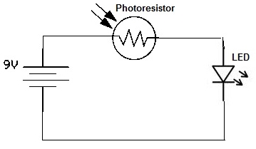
The photoresistor circuit consists of a few essential components: a photoresistor (LDR), an LED, a resistor, and a power source. The photoresistor, which changes resistance based on light intensity, is the core element of this circuit. When light hits the photoresistor, its resistance decreases significantly, allowing a greater current to flow through the circuit. This current flows through the LED, causing it to emit light.
A resistor is typically included in series with the LED to limit the current flowing through it, preventing damage from excessive current. The value of this resistor can be calculated based on the LED's forward voltage and the desired current, using Ohm's Law (V = IR).
The power source can be a battery or a DC power supply, providing the necessary voltage for the circuit. The circuit can be assembled on a breadboard for prototyping purposes, allowing for easy adjustments and testing.
In applications where the circuit is intended to function inversely (LED on in darkness), a different configuration involving a transistor may be employed. In such a case, the photoresistor would control the base of the transistor, allowing it to switch the LED on when the light level drops below a certain threshold. This versatility of photoresistors makes them suitable for various light-sensitive applications, such as automatic night lights, street lighting, and other systems requiring light detection.
Overall, understanding the operation and configuration of a photoresistor circuit lays the foundation for more complex electronic designs that harness light sensitivity for practical uses.Now we will build a very simple photoresistor circuit to make a photoresistor do what it does: make the circuit work when there is light and stop working when there is darkness. For this circuit, we connect a photoresistor to an LED. When the photoresistor is exposed to light, the LED is on and stays lit. When the photoresistor is exposed to darkn ess, the LED turns off and does not light. This project demonstrates the function of a photoresistor. This is the photoresistor circuit when the photoresistor is exposed to light. When exposed to light, the photoresistor has very little resistance, so current can flow through the circuit. The LED receives current and lights up; it stays lit as long as the photoresistor is exposed to light.
This is the photoresistor circuit when the photoresistor is exposed to darkness. When exposed to darkness, the photoresistor has very high resistance, so current cannot flow through the circuit. The LED receives no current and, thus, does not light up. The LED stays off as long as the photoresistor is exposed to darkness. In this circuit, the LED turns on when the photoresistor is exposed to light and turns off when the photoresistor is exposed to darkness.
To learn how to build the circuit so that it`s the other way around- so that the LED turns on when the photoresistor is exposed to darkness and turns off when exposed to light, see How to Build a Dark-activated Light Circuit. This is a more practical and useful circuit, because we need light more when it`s dark rather than when it`s bright.
This basic circuit was illustrative in that it showed the basic principles of how a photoresistor worked. However, to use it for more advanced and useful circuits, using a photoresistor to turn on a light when it`s dark is more useful.
🔗 External reference
Related Circuits
The refrigerator turned on, causing the lights to brighten. Initially, it seemed like an illusion, but after observing multiple cycles, the phenomenon persisted. When the microwave was activated, the lights dimmed. The refrigerator's operation appeared to influence the brightness...
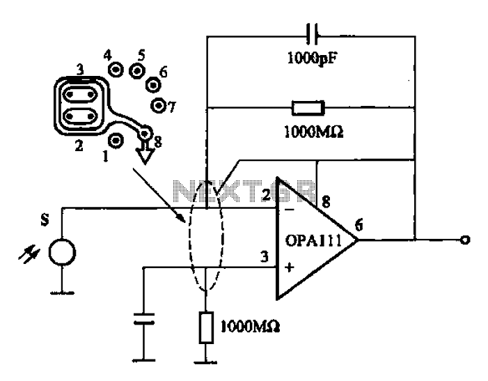
Infrared heat is emitted by an object during non-contact temperature measurement. The measured signal is weak, necessitating the use of highly sensitive thermal infrared sensors with minimal noise. Consequently, the amplifier circuit must also meet stringent requirements, as standard...
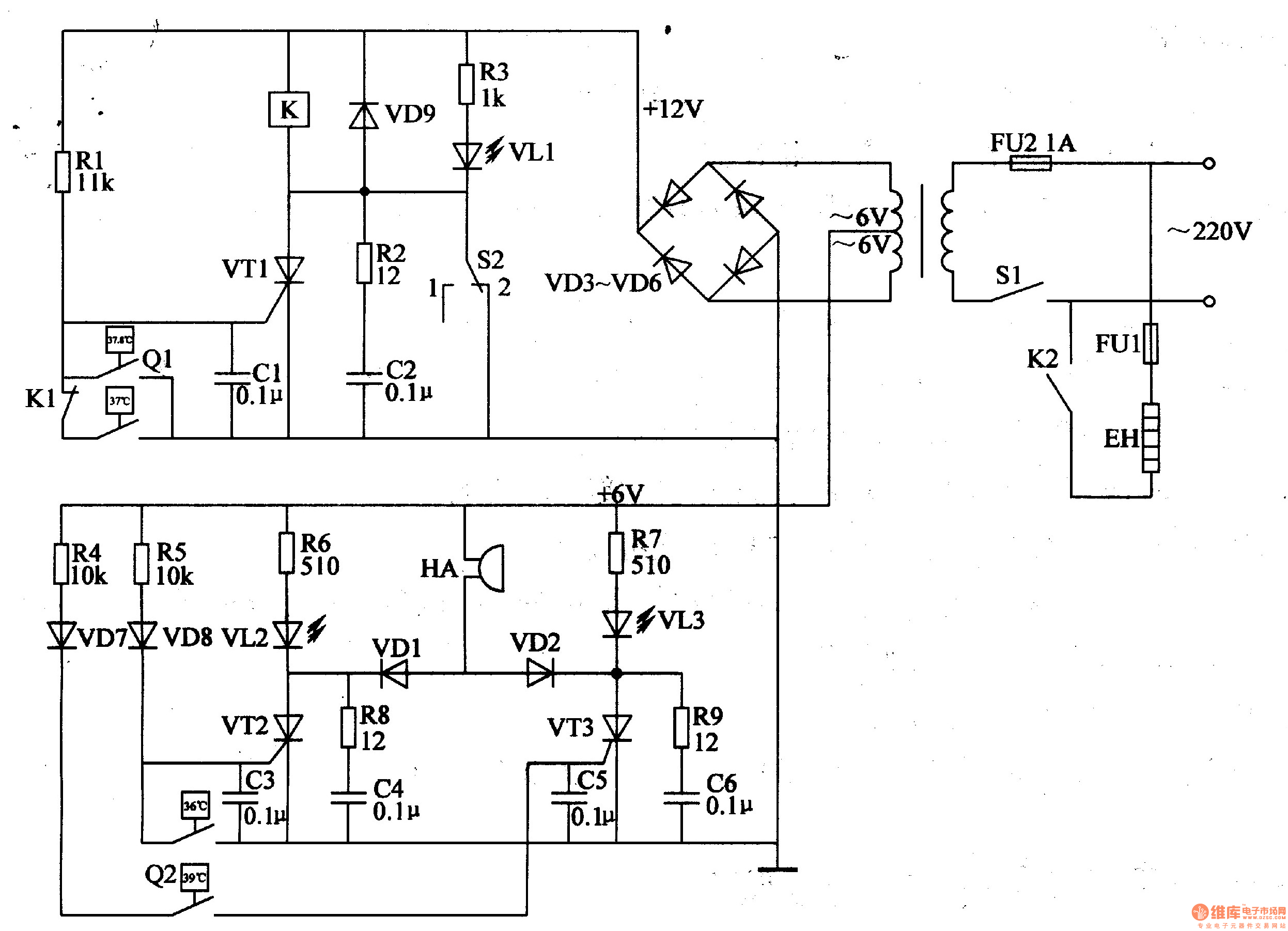
The egg hatching incubator circuit comprises a power supply circuit, a constant temperature control circuit, and a sound and light alarm circuit, as illustrated in Figure 4-7. The power supply circuit includes a power switch (S1), a fuse (FU2),...
This is an FSK modulation circuit composed of the 74LS74. The FSK modulation circuit does not include a phase-locked loop (PLL) or a high-Q bandpass filter, eliminating the need for tuning adjustments in the high-frequency modulation circuit. The two...
Pressing the pushbutton on the transmitter activates a sound and/or light alert in the receiver. This system operates without wiring or radio frequencies; instead, the transmitted signal is conveyed through the mains supply line. It is suitable for use...
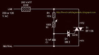
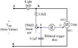
The circuit operates by adjusting the firing angle of the Triac. Resistors R1, R2, and capacitor C2 are involved in this process. The firing angle can be modified by changing the value of any of these components, with R1...