
13.8Vdc 2A Regulated Power Supply Circuit
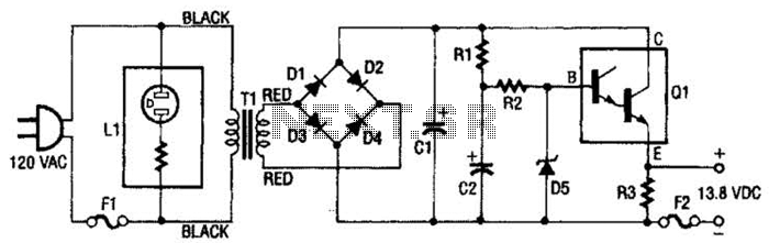
The described regulated power supply is a critical component in various electronic applications, providing a stable voltage output from a high-voltage AC source. The step-down transformer T1 plays a pivotal role in reducing the input voltage from 120 Vac to a safer 28 Vac, suitable for further processing. The full-wave rectifier bridge, composed of diodes D1 through D4, converts the alternating current (AC) output from the transformer into pulsating direct current (DC). This conversion is essential for powering DC devices.
Capacitor C1 functions as a smoothing capacitor, effectively filtering the pulsating DC output to provide a more stable DC voltage. It stores charge and releases it as needed, thereby reducing voltage ripple and ensuring a consistent output voltage. In conjunction with capacitor C2, which may be used for additional filtering or stability, the circuit can handle transient loads more effectively.
The Zener diode D5 is a crucial component in voltage regulation. By maintaining a constant voltage across the base of the Darlington transistor Q1, it ensures that the output voltage remains stable, even with variations in load current. This regulation is vital for sensitive electronic circuits that require a specific voltage for optimal performance. The Darlington pair configuration in Q1 allows for high current gain, making it suitable for driving larger loads while maintaining low output impedance.
Resistor R3, connected to the output, serves to limit the current and protect the circuit from overcurrent conditions. The presence of fuse F2 adds an additional layer of safety by disconnecting the circuit in the event of excessive current flow, thus preventing damage to the components.
Overall, this regulated power supply design is robust and reliable, suitable for various applications where stable DC voltage is required. Proper precautions must be observed when working with 120 Vac sources to ensure safety and prevent electrical hazards. This regulated power supply consists of step-down transformer Tl, a full-wave rectifier bridge (D1 through D4), and a filtering regulator circuit made up of Cl, C2, Rl, R2, R8, D5, and Ql, When 120 Vac is provided, the neon-lamp assembly LI lights up, and transformer Tl changes 120 Vac to about 28 Vac. The rectifier bridge, )1 through D4, rectifies the ac into pulsating dc, which is then filtered by Cl.
Capacitor Cl acts as a storage capacitor. Zener diode 1)5 keeps the voltage constant across the base of Darlington regulator Ql, causing constant voltage across resistor R3 and the (+) and (-) output terminals, where the load is connected. Fuse F2 is used to open (blow), if the current through the output terminals is too high. Make sure to take proper precautions when using projects powered by 120 Vac. 🔗 External reference
Related Circuits
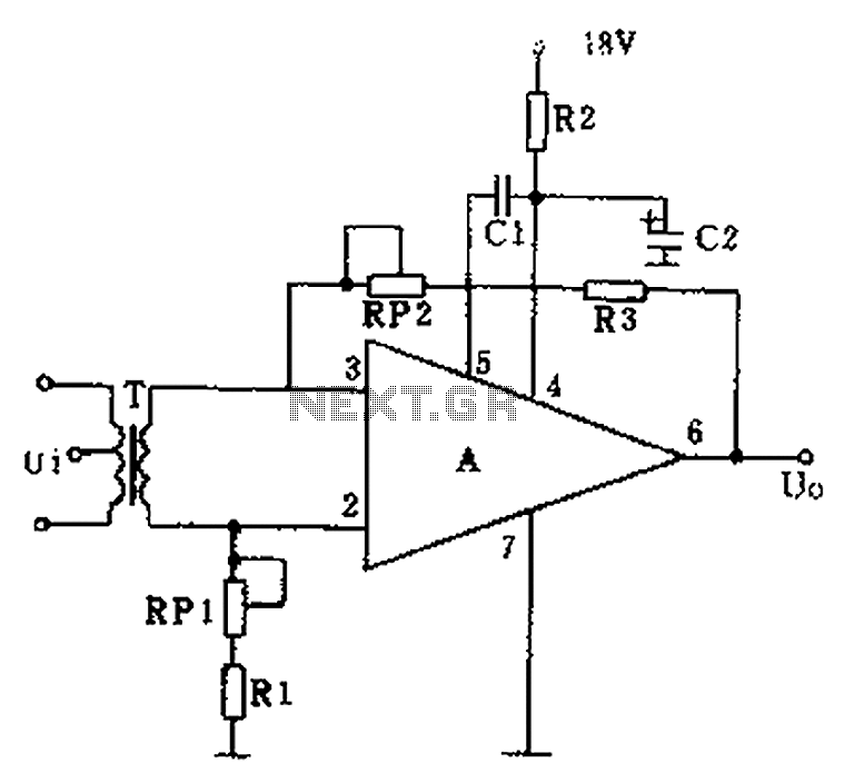
The operational amplifier A is utilized in an audio preamplifier circuit. Its advantages include compact size, low noise, low power consumption, and excellent consistency. The operational amplifier can achieve significant negative feedback while increasing output without distortion. The signal...
The LED flasher circuits below operate on a single 1.5 volt battery. The circuit on the upper right uses the popular LM3909 LED flasher IC and requires only a timing capacitor and LED. The top left circuit, designed by...
Assistance is needed in analyzing a circuit, specifically regarding the frequency cut-off between the bass and treble channels. The potential cut-off frequencies under consideration are 500Hz, 1KHz, or 5KHz. In audio processing circuits, the frequency cut-off point between bass and...
If a NiCad battery is discharged to the point where the lowest capacity cell becomes fully discharged and reverses polarity, that cell will typically short internally and become unusable. To prevent this type of damage, this circuit detects a...
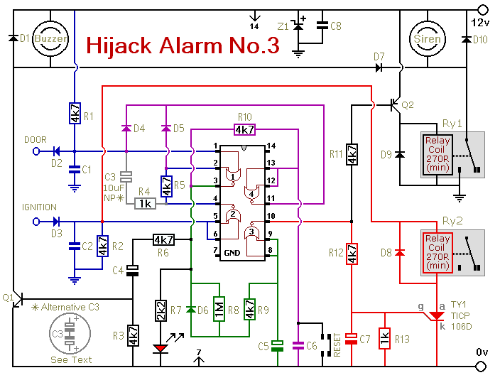
Similar to the initial two Hijack Alarms, this circuit is designed to activate if a door is opened while the ignition is switched on. After a delay of several minutes, allowing the thief to move a safe distance away,...
A car inverter, also known as a power converter or power inverter, is a device that converts 12V DC from a vehicle’s electrical system into 220V AC for general electrical use. It serves as a convenient power adapter for...