
Simple Toy Organ using 555
The described circuit functions as a basic oscillator, utilizing multiple resistors configured in series to determine the oscillation frequency. The core component of this oscillator is the 555 timer IC, which operates in astable mode to generate a square wave output. The frequency of oscillation can be adjusted by incorporating variable resistors (potentiometers) in place of fixed resistors, allowing for fine-tuning of the output frequency to match musical notes.
Each switch in the circuit is connected to the trigger input of the 555 timer, enabling the oscillator to initiate oscillation upon activation. However, the design limits the ability to press multiple keys simultaneously, as each switch's activation alters the timing components and subsequently the frequency output. This characteristic is essential for the intended application as a simple electronic organ.
For a more complex instrument capable of polyphony (multiple keys pressed simultaneously), the use of multiple 555 timer ICs is necessary. Each IC would be dedicated to a single note, with its own set of resistors and capacitors to define its frequency. The recommendation of using between 9 to 12 volts as the power supply is standard for 555 timer circuits; however, caution is advised due to potential loudness and the risk of electrical shock when using higher voltage supplies.
Furthermore, the audible "hum" mentioned is a common artifact in oscillator circuits, often resulting from power supply noise or the inherent characteristics of the 555 timer. To mitigate this, additional filtering components such as capacitors may be employed to smooth out the power supply and reduce unwanted noise.
In summary, this simple oscillator circuit, while effective for generating sound, has limitations in terms of simultaneous key presses and noise levels, necessitating careful design considerations for more advanced applications in electronic musical instruments.This is a simple oscillator with multiple resistors in serie. When you press any switch, the circuit starts oscillating. You can user variable resistors instead the 1k resistors. Using variable resistors you will be able to tune the frecuency for each note. You cannot be able to press two keys at the same time because the frecuency will change. To make an electronic organ capable to press many keys at the same time, you may need to use thirteen 555 ICs. Is ok to use 9 to 12V as power but it may be quite loud. I do not recommend to use a power supply as it may cause electrical shock. Also a "hum" will be audible while it is in use. 🔗 External reference
Related Circuits
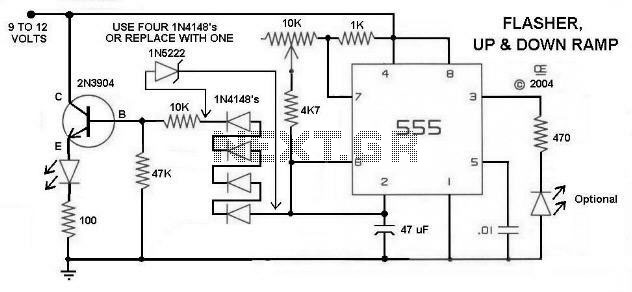
Here is a Simple Circuit to give a Flashing LED, With a "Rising and Falling" Brightness. It Uses the Sawtooth waveform from pins 2 and 6 to create the rise and fall. The Resistor and LED on Pin 3...
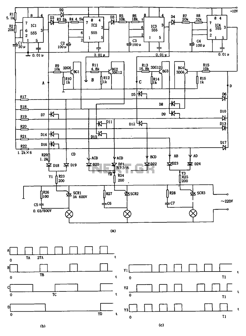
The decorative lamp control circuit is illustrated in the figure. The controller comprises a pulse generator, a frequency divider, a matrix circuit, and a thyristor control circuit. Components IC1, R1, R2, C1, and others form a multivibrator where the...
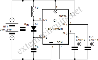
An EL lamp is a solid-state, low-power, uniform area light source. Due to its thin profile (as thin as 0.3 mm) and its capability to be manufactured in various sizes and shapes, EL lamps serve as an ideal solution...
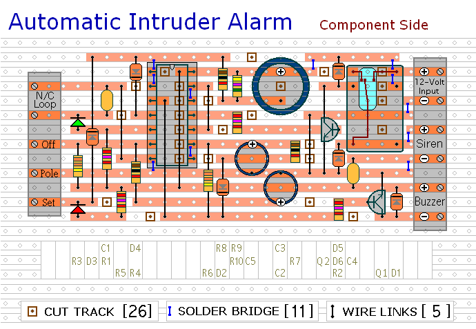
This circuit includes automatic exit and entry delays, a timed bell cut-off, and a system reset feature. It is designed to work with standard normally-closed input devices such as magnetic reed contacts, micro switches, foil tape, and passive infrared...
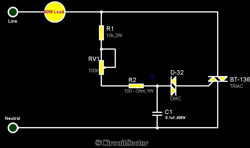
The circuit diagram presented is a triac-diac electronic fan regulator designed to reduce power consumption of electric fans, even at low speeds. Traditional resistor-inductor fan regulators tend to generate excess heat, wasting energy when the fan operates at lower...
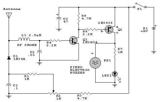
This electronic RF detector project is designed using common transistors and a few standard electronic components. The RF detector responds to RF signals below the standard broadcast band and well over 500 MHz, providing both visual and audible indications...