
Simple Pulse Stretcher

The circuit described utilizes an open collector configuration, which is commonly employed in digital logic applications to create a one-shot pulse generator. The operation relies on the characteristics of the open collector output, which can effectively pull the output low while allowing an external resistor to pull it high when not actively driven low.
In this configuration, the pulse duration is determined by both a specified time interval 't' and the time constant associated with the resistor-capacitor (RC) network, denoted as RiCi. The time constant is critical as it defines how quickly the capacitor charges and discharges, directly influencing the length of the output pulse.
The resistor R2, functioning as a pull-up resistor, is connected between the supply voltage and the output of the gate. This arrangement ensures that the output remains high when there is no active pull-down from the open collector. When the gate is triggered, it drives the output low, allowing the capacitor in the RC network to charge or discharge based on the circuit's design. The combination of the resistor and capacitor values determines the pulse width, which is essential for applications requiring precise timing control.
In summary, this open collector one-shot circuit is a versatile component in digital electronics, providing reliable pulse generation with adjustable timing characteristics through the careful selection of resistor and capacitor values. A single gate (open collector, noninverting) produces a simple one-shot to produce a pulse that stretches equal to t he pulse duration, plus the RiCi time constant. R2 is a pull-up resistor to keep the gate"s input high while waiting for a pulse.
Related Circuits
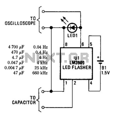
An LM3909 LED flasher functions as an oscillator, with the frequency determined by the capacitor connected to its terminals. The LED can be utilized to visually count frequency using a stopwatch for large capacitors (C > 500µF). The LM3909 is...

FIG IC, ICR, Ri, R, and AN composition form a bistable contact circuit with a Ge transistor. It includes components such as ICc, lc, c2, and Dj, and is associated with a one-shot delay circuit. The circuit can be...
This circuit is utilized in a multiplier that operates with one of the operational amplifiers in an analog computer. The double-triode V1 in this configuration provides pulse-amplitude modulation, which is intended for use with a separate pulse-width modulator to...
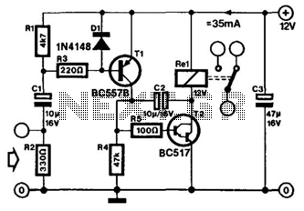
The human approach detector circuit consists of an integrated operational amplifier, a gate circuit, and a resistor-capacitor unit as illustrated in the diagram. The 1 MHz oscillator is composed of a reverser T1, a 1 MHz crystal oscillator, and...
A VOX is a voice-operated switch that is often used as a substitute for the press-to-talk switch on a microphone. This VOX can be connected to almost any audio equipment that has a socket for an external loudspeaker. The...
This simple tuned radio frequency receiver was designed and constructed in the mid-1990s. The receiver was tested under urban and field conditions, in varying temperatures. This straightforward circuit exhibits high sensitivity, good sound quality, and reliability. A signal received...