
A simple tuned radio frequency receiver
The tuned radio frequency receiver operates by utilizing a ferrite rod loop antenna, which is effective for capturing radio signals across various frequencies. The resonant tank circuit, composed of inductor L1 and capacitor C, is critical for selecting the desired frequency while rejecting others. The coupling coil L2 facilitates the transfer of the received signal to the reflex amplifier, which amplifies the signal in two stages using transistors VT1 and VT2. This design enhances the overall gain and sensitivity of the receiver.
The envelope detector plays a vital role in demodulating the received amplitude-modulated (AM) signals. The use of a biased diode VD1 allows the circuit to effectively handle weak signals, while the RC filter smooths the output, providing a clean audio signal. The feedback mechanism through the amplifier ensures that the gain is adjusted dynamically based on the signal strength, thereby maintaining audio quality.
The audio amplifier stage, utilizing transistor VT3, is designed to drive headphones with a specific impedance. The low-pass filter preceding this stage ensures that only the desired audio frequencies are passed, minimizing distortion and enhancing sound clarity.
The design's flexibility allows for the use of various antennas and capacitors, making it adaptable to different applications. The compact nature of the PCB and the housing ensures portability, while the placement of the volume control potentiometer enhances user convenience. Overall, this receiver circuit exemplifies a robust design for effective radio signal reception and audio output.This simple tuned radio frequency receiver (Fig. 1) was designed and constructed in the mid 1990s. The receiver was tested under urban and field conditions, in the heat and cold. This simple circuit has quite high sensitivity, good sound quality and reliability. A signal received by a ferrite rod loop antenna WA1 and applied to a resonant tank L1C 1, passes through the coupling coil L2 to the two-stage transistor amplifier (VT1, VT2). This is the reflex amplifier. The amplified signal from the resistor R4 is fed to the envelope detector that consists of a diode VD1 and a RC filter R3C4. The diode is biased, the bias depends on the operating mode of transistors. The operating mode may be adjusted by the potentiometer R5. Due to the bias, the detector works well for receiving weak signals. The audio signal from the detector goes back to the same amplifier (VT1, VT2). From the output of the amplifier the audio signal passes through the low pass filter R6C5 to an audio amplifier based on the transistor VT3.
The load of this amplifier is headphones TA-56M (1600 Ohms) connected to the terminals X1. A negative voltage, proportional to the amplitude of the signal appears at the output of the detector. This negative voltage opens the transistors VT1, VT2 and changes the bias of the detector, reducing its gain.
When receiving AM signals, a negative audio feedback across the detector improves the linearity of detection. The result is high quality sound. In this circuit may be used any suitable loopstick antenna and a variable capacitor from any portable radio receiver.
The components are mounted on a PCB, the PCB is placed in any suitable plastic housing. The potentiometer R5 (volume control) is mounted on a side of the housing. In some cases the potentiometer can help to reduce the interferences. The circuit doesn`t require alignment. The voltage of the power supply is 4. 5 V, which is formed by serially connecting three batteries of 1. 5 V. The consumption current is about 10 mA (when there is no signal). 🔗 External reference
Related Circuits
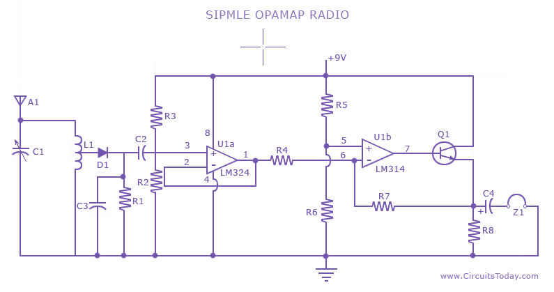
A low-cost, simple radio circuit schematic using an operational amplifier. This radio circuit diagram consists of a sensitive audio amplifier that receives strong signals. The presented radio circuit schematic utilizes an operational amplifier (op-amp) to create a cost-effective and straightforward...
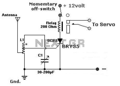
The diagram illustrates a simple and efficient receiver designed for controlling garage doors, starter motors, alarms, warning systems, and various other applications. The SCR utilized in this circuit features an exceptionally low trigger current of 30 µA. The circuit operates...
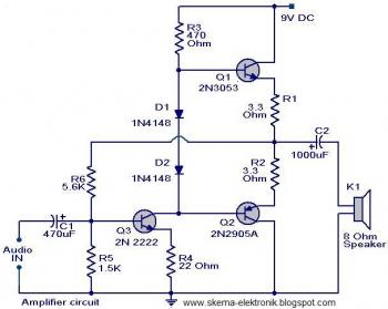
The initial section of the circuit is a preamplifier that utilizes transistor Q1 (2N2222). The collector of transistor Q3 is connected to the base of transistor Q2 (2N2905A), which creates a complementary symmetry pair with Q3 (2N3053). The amplified...
Here are the schematics for infrared remotes. This remote transmits a tone using an infrared LED. This tone is decoded by the receiver. Since the receiver only switches when it "hears" the tone, there are no accidental activations. The schematic...

Phase noise is a critical performance parameter of frequency synthesizers for wireless applications. RF system designers of phase-modulated cellular systems, such as PHS, GSM, and IS-54, require low noise local oscillator (L.O.) or frequency synthesizer blocks. This document describes...
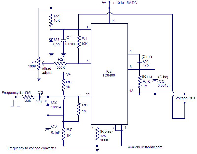
A simple and low-cost frequency-to-voltage converter based on the TC9400 IC from Microchip is presented. The TC9400 can be configured as either a voltage-to-frequency converter or a frequency-to-voltage converter, requiring minimal external components. The internal functional blocks of the...