
simple servo motor controller circuit

The servo motor is a critical component in many electronic applications due to its precision and reliability in positioning. It operates based on the principles of pulse-width modulation (PWM), where the duration of the pulse sent to the servo determines its angle of rotation. The 555 timer is employed in this circuit to generate the PWM signal, allowing for effective control of the servo's position.
In the circuit, the 555 timer is configured in astable mode, producing a continuous square wave output. The frequency and duty cycle of this signal can be adjusted by varying the resistances and capacitance in the circuit. A potentiometer is integrated into the design, allowing the user to manually set the desired angle of the servo. As the potentiometer is adjusted, it changes the voltage level fed into the control pin of the servo, thus altering its position accordingly.
For the PCB fabrication process, it is essential to ensure that the design is accurate and free from errors. The use of PCB design software, such as Eagle, facilitates the creation of a schematic and layout that can be easily transferred to the PCB. After printing the design, special care must be taken when adhering it to the PCB to avoid air bubbles that could affect the etching quality. The heating process should be done uniformly to ensure that the ink adheres properly to the copper surface.
Following the transfer of the design, the etching process can be initiated, usually involving a ferric chloride solution that removes the unprotected copper, leaving behind the desired circuit traces. Once etching is complete, the board can be cleaned, and components can be soldered onto the PCB, completing the assembly of the servo control circuit. This method provides a cost-effective and efficient way to create custom circuits for various applications involving servo motors.The servo motor have many utilizes in everything from robotics to puppetry to photography and beyond. These tiny motors can position their output shaft to any position on command and hold that position. Most servos possess a range of motion to about 210 degrees and thankfully are quite easy to handle with a basic circuit like the one presented rig
ht here. Working with just a 555 timer as well as a couple of support parts, this circuit can handle a servo via it is full rotation primarily based on the position of a potentiometer. Make a PCB in very easy steps. ! Create your PCB design using PCB designer software like Eagle, print out your design on photo paper or glossy paper with laserjet printer.
Stick the printed design on the PCB (copper side) and then heat it using hot iron plate. The ink will stick on the PCB and it will be ready for etching process. Note: If you don`t have laserjet printer, then you can print the design on standard paper. Copy the printed design at Copy Service around your location (with glossy paper). 🔗 External reference
Related Circuits
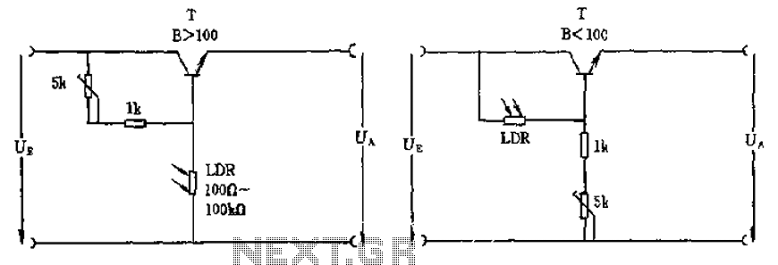
The circuit depicted involves a photoresistor (LDR) connected to a transistor, which operates at either a high or low level based on light conditions. The amplification factor of the transistor is 100, which is adequate for the application. The...
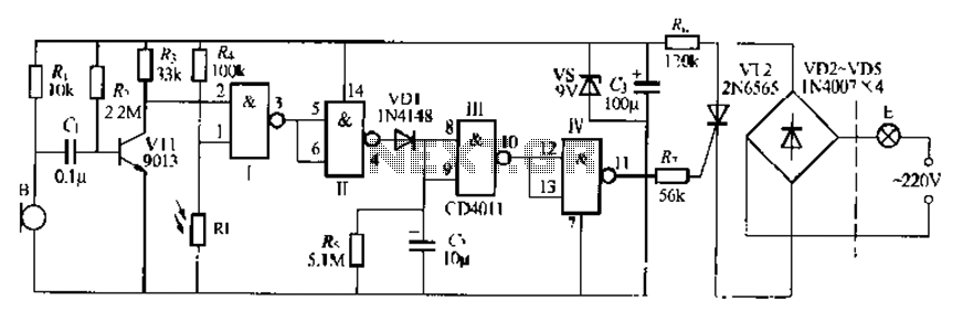
The CDI011 integrated circuit is designed for a sound and light-controlled stair delay switch circuit, which is relatively simple and effective. It utilizes a combination of NAND gates and differential input dynamics. The circuit has two input terminals; when...

Low Ripple Regulated Power Supply Circuit Diagram. This circuit can be employed in applications requiring high current with minimal ripple voltage, such as in high-powered class AB amplifiers where high-quality audio reproduction is essential. The low ripple regulated power...

This is a single alarm circuit. The circuit includes automatic exit and entry delays, a timed bell cut-off, and a system reset. It has provisions for normally open and normally closed inputs. The single alarm circuit is designed to provide...
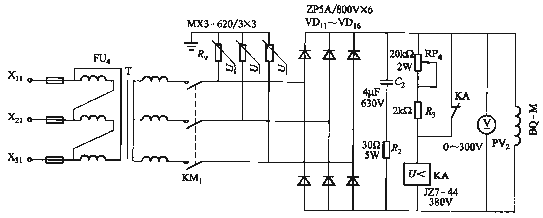
FIG T is the excitation transformer, R is a varistor, and there are rectifier diodes to protect against breakdowns from VDii to VD16; Rz and C2 provide resistive-capacitive protection. The circuit is designed to absorb voltage from the magnetic...
This circuit generates dual-tone bell ringing similar to most doorbell units. It can be used in various applications beyond just doorbells. Several options will be provided in the notes to accommodate different needs. The circuit, as depicted in the...