
3904 3906 Siren Circuit
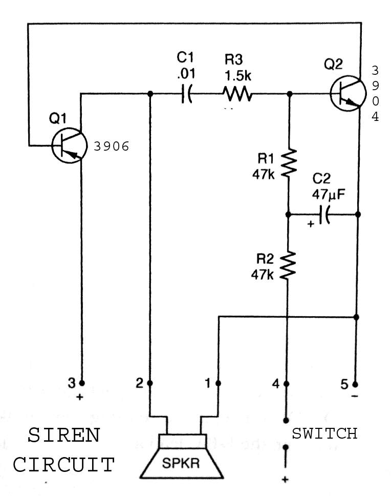
The 3904 3906 Siren Circuit is designed to produce a distinctive wailing sound, commonly used in alarm systems and signaling devices. The circuit utilizes bipolar junction transistors (BJTs) 3904 and 3906, which function as the primary amplifying elements.
When the circuit is powered on by activating the switch, the initial current flows through the base of the 3904 transistor, causing it to enter saturation. This action triggers the 3906 transistor, which is configured in a complementary arrangement, allowing it to also conduct. The interaction between these two transistors creates a feedback loop that leads to rapid oscillations.
The frequency of the oscillation can be adjusted by incorporating passive components such as resistors and capacitors in the feedback path. Typically, a capacitor is connected between the collector of the 3904 transistor and the base of the 3906 transistor, while a resistor is placed in series with the base of the 3904 transistor. This configuration determines the charging and discharging time of the capacitor, thereby controlling the pitch and duration of the siren sound.
Additional components may include a loudspeaker or piezoelectric element to convert the electrical signal into audible sound. The circuit may also include diodes for protection against back EMF if inductive loads are used.
Overall, the 3904 3906 Siren Circuit is an effective and straightforward solution for generating a wailing siren sound, suitable for various applications in security and alert systems.3904 3906 Siren Circuit. The circuit produces a wailing siren sound when the switch is turned on.. 🔗 External reference
Related Circuits
This radio receiver can operate with any of the following transistors: ZN414, MK484, or TA7642. The radio receiver circuit is designed to utilize a variety of transistors, specifically the ZN414, MK484, and TA7642, which are commonly used in low-power AM...
The Clock Controller was designed to be an exemplary of using 'C' language to control timer0 interrupt, 7-segment LED and keypad scanning. It provides 1-bit sink current driving output, for driving a relay, opto-triac, say. Many projects requiring 7-segment...
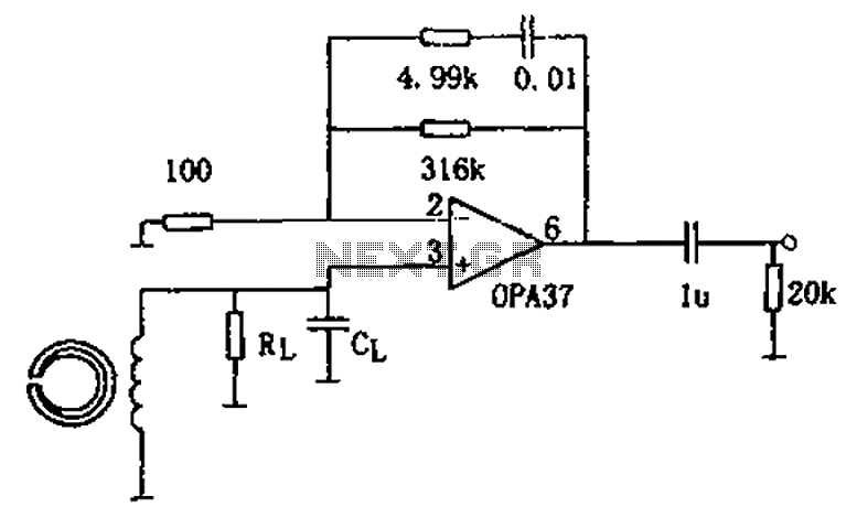
The circuit is a 90s common recorder head amplifier circuit that utilizes the ultra-low noise precision operational amplifier OPA37 as a preamplifier. This circuit is capable of providing standard NAB equalization. At a frequency of 1 kHz, it achieves...
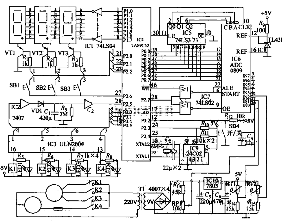
The circuit functions as a computer logo-conditioned temperature control system as depicted in Figure 1-58. The primary component is the AT89C52 microcontroller. When powered on, the 4C02 microcontroller first retrieves the last saved setpoint temperature and the operational state...
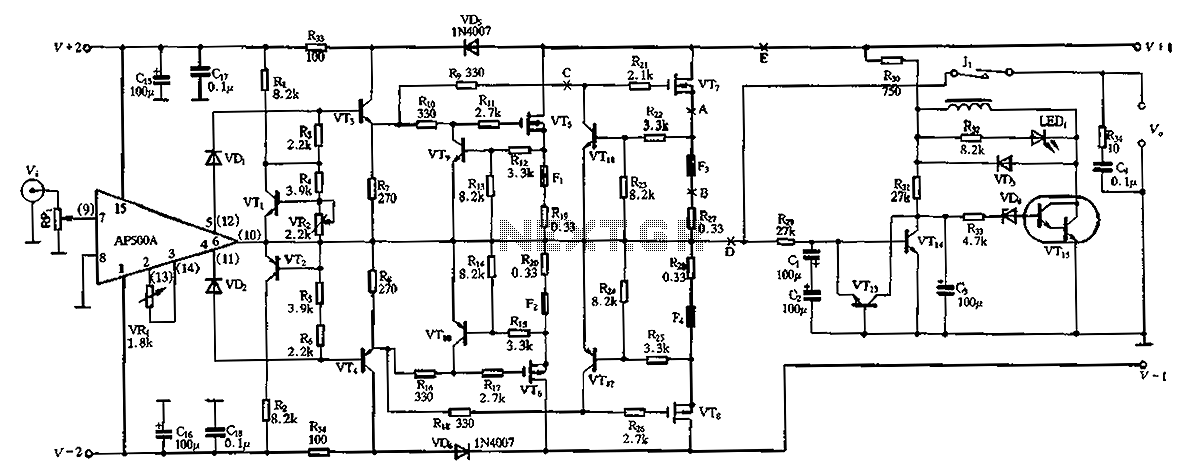
The CPI is a 100W DC super power amplifier circuit based on the AP500. It features a parallel push-pull amplifier output stage composed of transistors VT5, VT6, and VT7 to enhance output power. The circuit's output power is low...
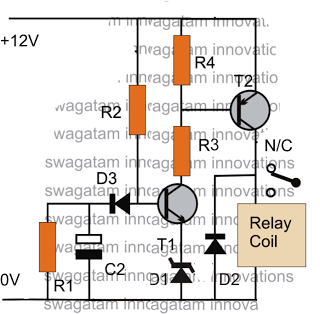
The post discusses a simple delay ON circuit that enables a connected load at the output to be activated with a predetermined delay after the power switch is turned ON. This circuit can be utilized in various applications that...
Warning: include(partials/cookie-banner.php): Failed to open stream: Permission denied in /var/www/html/nextgr/view-circuit.php on line 713
Warning: include(): Failed opening 'partials/cookie-banner.php' for inclusion (include_path='.:/usr/share/php') in /var/www/html/nextgr/view-circuit.php on line 713